Integrated processes for propylene production and recovery

a propylene and process technology, applied in the direction of hydrocarbon preparation catalysts, hydrocarbon oil treatment products, sustainable manufacturing/processing, etc., can solve the problems of significant reduction in the operation of combined propylene-containing streams and the cost of larger capacity equipment, so as to achieve significant capital and utility savings and reduce the effect of capacity

Active Publication Date: 2013-10-22
UOP LLC
View PDF19 Cites 37 Cited by
  • Summary
  • Abstract
  • Description
  • Claims
  • Application Information

AI Technical Summary

Benefits of technology

[0009]Aspects of the invention relate to the integration of (i) processes and the associated equipment used to purify and recover propylene from propane- and / or C4+-containing refinery hydrocarbon streams, with (ii) catalytic dehydrogenation. This integration allows for elimination of the conventional fractionation section of the dehydrogenation process, normally used to purify propylene from unconverted propane and other components in the reactor effluent. Significant capital and utility savings are therefore attained, due to the substantial energy and equipment requirements associated with this separation. The “sharing” of major separation equipment, which may include a depropanizer, a deethanizer, and / or a propane / propylene splitter, between propylene recovery and catalytic dehydrogenation processes provides important cost benefits relative to carrying out these processes separately.
[0010]In particular, combining process streams that benefit, in the integrated processes described herein, from being treated in a similar manner allows for the realization of economies of scale. That is, the added costs for larger capacity equipment (e.g., distillation columns) and its operation in processing combined propylene-containing streams is significantly less than that of duplicating at least some of the same or similar equipment in separate processes. Moreover, the use of integrated processes can, in some cases, render smaller capacity catalytic dehydrogenation units economically feasible when coupled with existing or planned propylene recovery processes.

Problems solved by technology

That is, the added costs for larger capacity equipment (e.g., distillation columns) and its operation in processing combined propylene-containing streams is significantly less than that of duplicating at least some of the same or similar equipment in separate processes.

Method used


Image

  • Integrated processes for propylene production and recovery
  • Integrated processes for propylene production and recovery
  • Integrated processes for propylene production and recovery

Examples


example 1

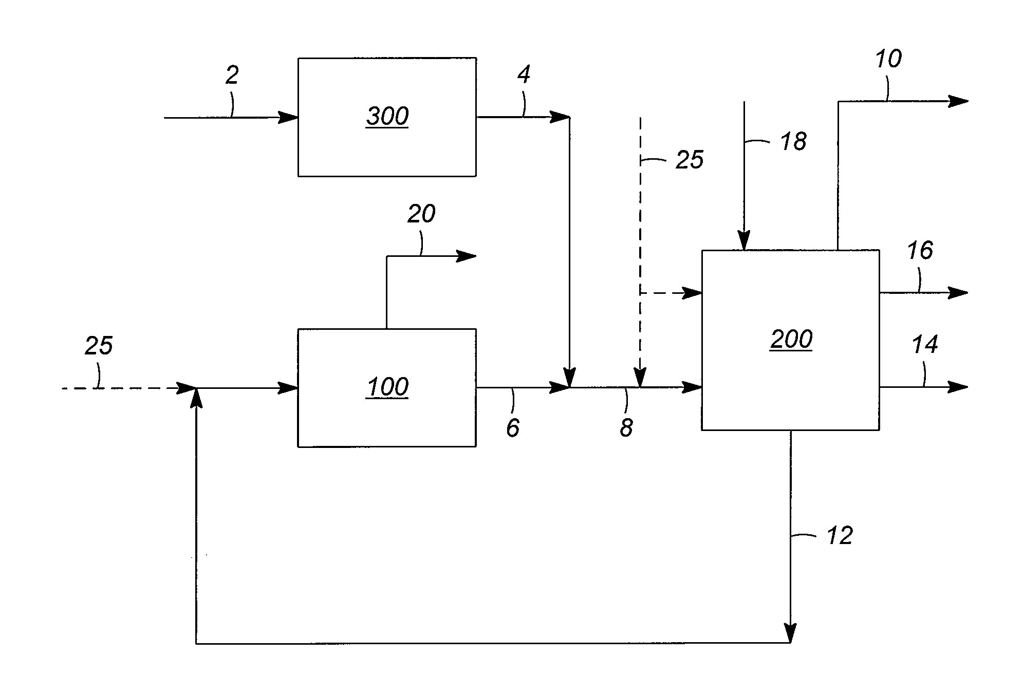
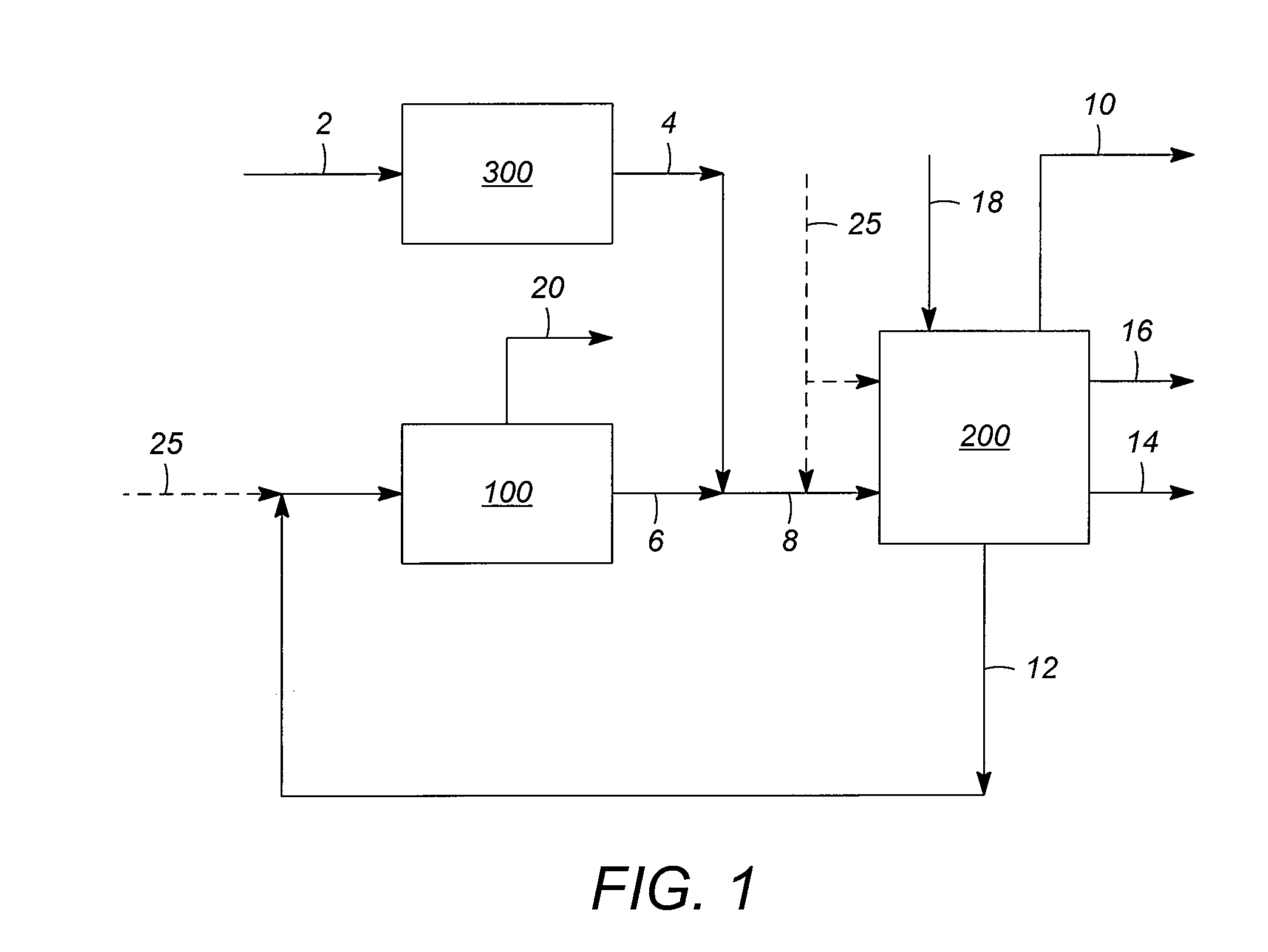
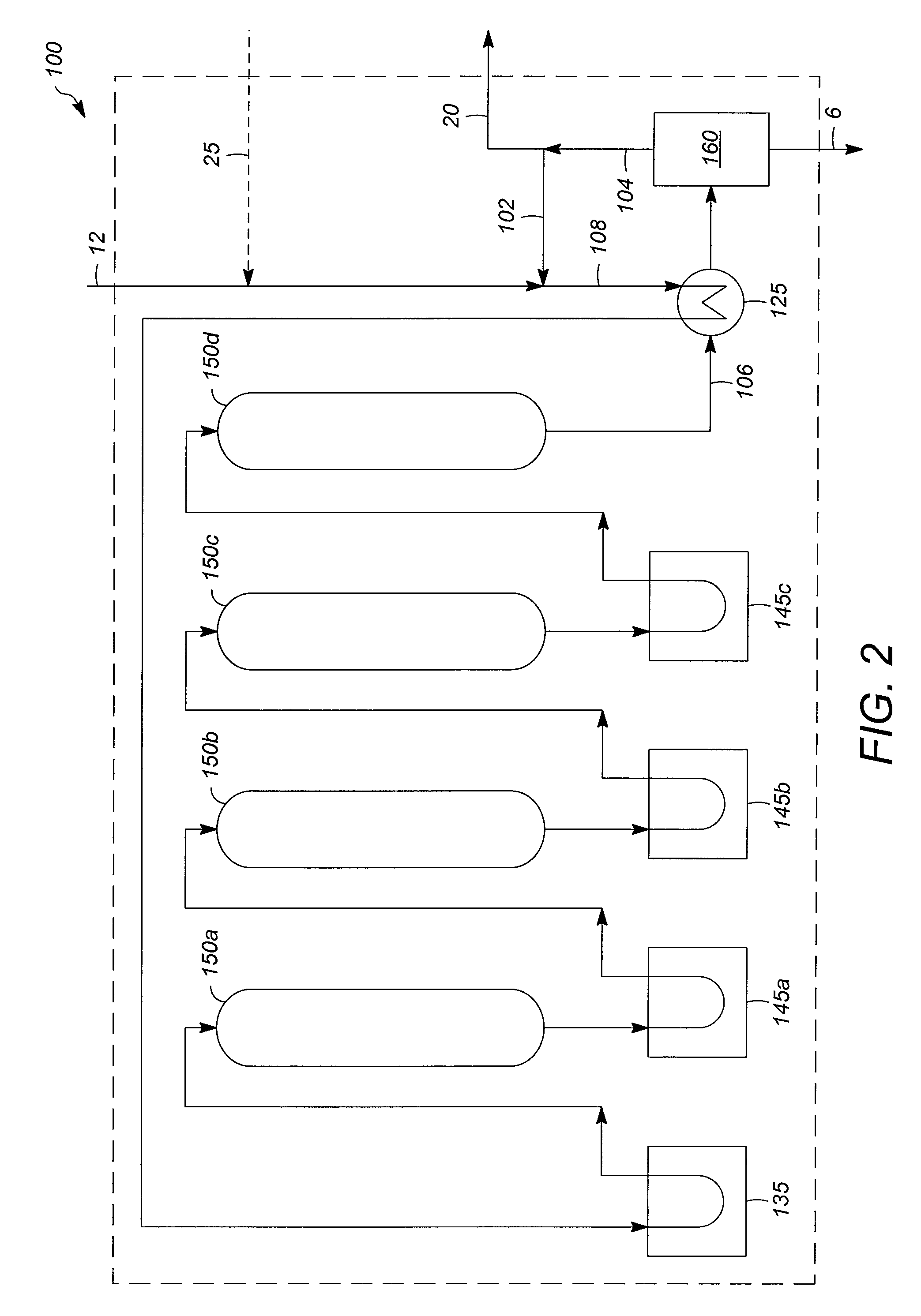
[0051]In the case of a commercial catalytic dehydrogenation process, namely the UOP Oleflex™ process for production of propylene from propane, the product fractionation section comprising a depropanizer, a deethanizer, and a propane / propylene splitter, was estimated to represent about 25% of the total erected cost of a unit for 250 kMTA of propylene production. This fractionation section can be effectively eliminated by increasing the capacity of a PRU used to process LPG from FCC for propylene recovery. The overall capital cost savings of integrating a PRU with an Oleflex™ process to consolidate the fractionation sections of these processes, according to the present invention, is estimated to be about 10-15%. This savings can be sufficient to render smaller capacity processes for propylene production economically feasible, depending on the price of propylene relative to propane and other factors.


PUM

PropertyMeasurementUnit
temperatureaaaaaaaaaa
pressureaaaaaaaaaa
temperatureaaaaaaaaaa

Abstract

Processes utilizing the integration of (i) processes and the associated equipment used to purify and recover propylene from propane- and / or C4+-containing refinery hydrocarbon streams, with (ii) catalytic dehydrogenation are disclosed. This integration allows for elimination of some or all of the conventional fractionation section of the dehydrogenation process, normally used to purify propylene from unconverted propane in the reactor effluent. Significant capital and utility savings are therefore attained.

Description

FIELD OF THE INVENTION[0001]The invention relates to processes for propylene production and more particularly to the dehydrogenation of propane recovered from catalytic cracking processes such as fluid catalytic cracking (FCC).DESCRIPTION OF RELATED ART[0002]Propylene demand in the petrochemical industry has grown substantially, largely due to its use as a precursor in the production of polypropylene for packaging materials and other commercial products. Other downstream uses of propylene include the manufacture of acrylonitrile, acrylic acid, acrolein, propylene oxide and glycols, plasticizer oxo alcohols, cumene, isopropyl alcohol, and acetone. Currently, the majority of propylene is produced during the steam cracking or pyrolysis of hydrocarbon feedstocks such as natural gas, petroleum liquids, and carbonaceous materials (e.g., coal, recycled plastics, and organic materials), to produce ethylene. Additional significant sources of propylene are byproducts of fluid catalytic cracki...

Claims


Application Information

Patent Timeline
Patent Type & Authority Patents(United States)
IPC IPC(8): C07C5/333C07C7/04C07C5/09C10G11/00
CPCC07C5/05C07C5/09C07C5/333C07C5/3337C07C7/04C07C7/09C07C11/06C07C2521/04C07C2523/42C07C2523/755C07C2527/02C10G2400/20Y02P20/10
Inventor ZIMMERMANN, JOSEPH E.ERICKSON, LARRY C.NEDOHIN, GREGORY J.
Owner UOP LLC
Why Eureka
Try Eureka