Illumination device with LED and one or more transmissive windows

a technology of a transmission window and an illumination device, which is applied in the direction of discharge tube luminescent screens, lighting and heating apparatus, instruments, etc., can solve the problems of stress gradient, film cracking, curling and even delamination, etc., and achieves high luminescent material, thick luminescent material layer, good flowing properties

Inactive Publication Date: 2013-10-29
KONINK PHILIPS ELECTRONICS NV +1
View PDF23 Cites 11 Cited by
  • Summary
  • Abstract
  • Description
  • Claims
  • Application Information

AI Technical Summary

Benefits of technology

[0005]A disadvantage of the prior art systems may be that in modules where the light is not recycled multiple times before being emitted from the system (as is the case in e.g. LCD backlighting modules), and in particular for the generation of warm white light, a relatively highly luminescent material load per unit area and, as a result, a very thick luminescent material layer, may be required. The luminescent material dilution in the matrix material should be sufficient to enable good flowing properties, which may result in relatively very thick layers of binder material comprising the luminescent material particles, which may hamper the coating process and may result in stress gradients due to different material properties of the film and the coating. This can easily result in film cracking, curling and even delamination.

Problems solved by technology

A disadvantage of the prior art systems may be that in modules where the light is not recycled multiple times before being emitted from the system (as is the case in e.g. LCD backlighting modules), and in particular for the generation of warm white light, a relatively highly luminescent material load per unit area and, as a result, a very thick luminescent material layer, may be required.
The luminescent material dilution in the matrix material should be sufficient to enable good flowing properties, which may result in relatively very thick layers of binder material comprising the luminescent material particles, which may hamper the coating process and may result in stress gradients due to different material properties of the film and the coating.
This can easily result in film cracking, curling and even delamination.
This required adaptation of the luminescent material coating suspension may lead to significant waste of material because the pre-mixed material generally cannot be used any more.
On-the-fly closed loop control of the film properties in a roll-to-roll process is very difficult with the single mixture.
Another problem in the prior art may be that a mixture of luminescent materials may lead to significant luminescent material interaction for most luminescent materials of interest for illumination.
The yellow-green light emitted from one luminescent material (or luminescent material mixture) may often be absorbed partly by the red-orange emitting luminescent material (or luminescent material mixture), resulting in a lower overall system efficacy (because of the additional quantum efficiency losses in the red-orange luminescent material) and a reduced color rendering because of changes in the spectral shape of the yellow-green light.
Typically this can result in a drop in CRI from e.g. 85 to 77, which makes the light in most applications unsuitable for general illumination tasks.
Furthermore, the luminescent material interaction may require more luminescent material, making the system more expensive.
Another disadvantage of the prior art systems may be that applying a luminescent material layer as an exit window or as material visible to a viewer may result in a color of the exit window, particularly a yellow-orange color, when the system is in the off-state.

Method used


Image

  • Illumination device with LED and one or more transmissive windows
  • Illumination device with LED and one or more transmissive windows
  • Illumination device with LED and one or more transmissive windows

Examples


Embodiment Construction

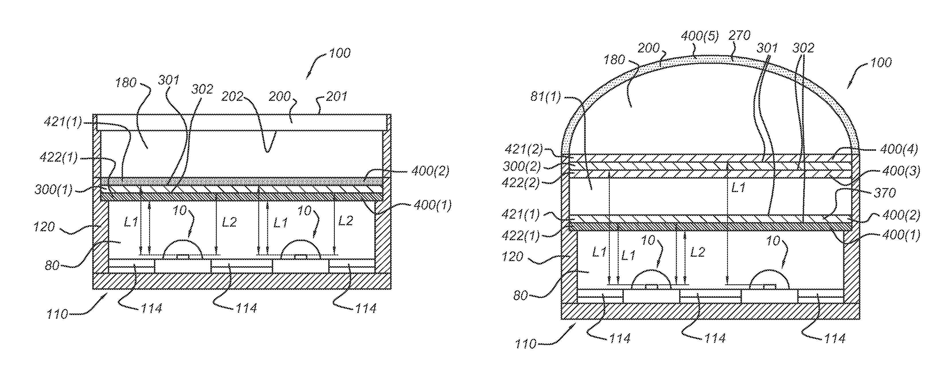
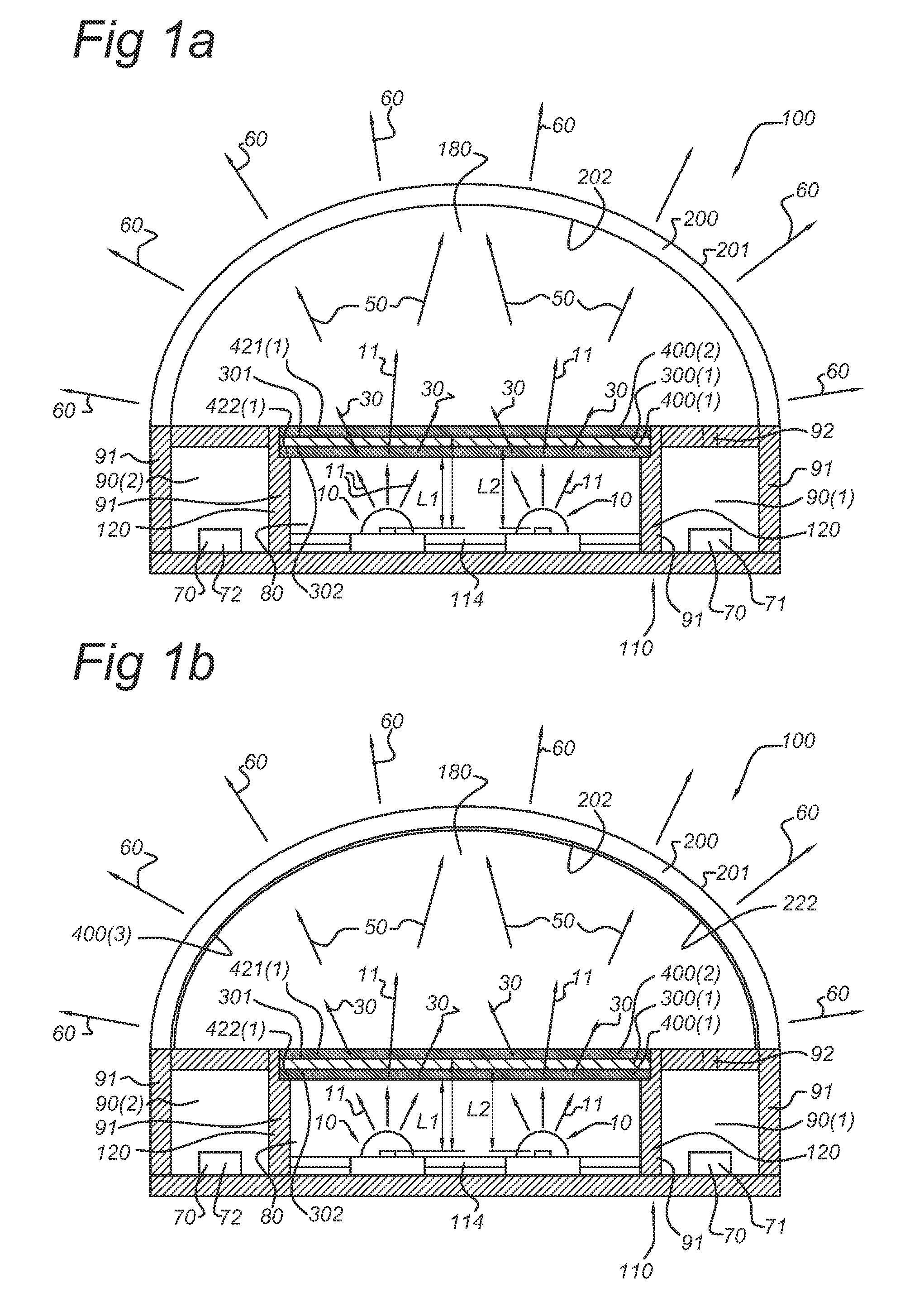
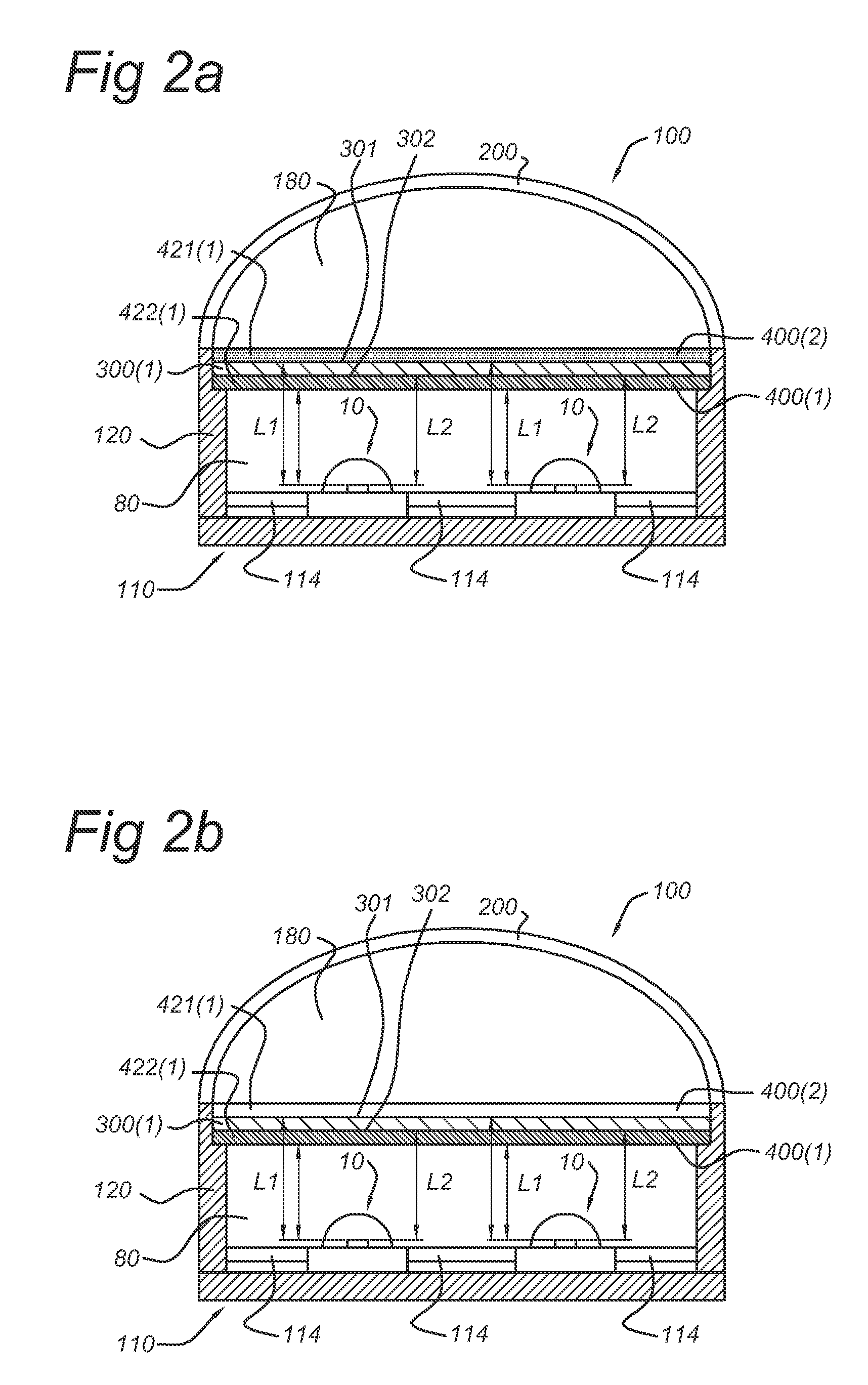
[0074]FIG. 1a schematically depicts an embodiment of the illumination device according to the invention. The illumination device is indicated with reference 100. The illumination device 100 comprises a light emitting diode 10 arranged to emit LED emission 11, which may for instance be blue light.

[0075]The illumination device 100 further comprises a translucent exit window 200, having an upstream exit window face 202 and a downstream exit window face 201. The latter is directed to the exterior and the former is substantially directed to the interior of the device 100, more particularly to the LED(s) 10. The translucent exit window 200 may for instance be frosted PC or glass.

[0076]In the schematically depicted embodiment of FIGS. 1a-1b, the translucent exit window 200 has a substantially convex shape.

[0077]Downstream of the LED(s) 10 and upstream of the translucent exit window 200, n transmissive windows 300(1), 300(2), . . . 300(n) are arranged, wherein n is equal to or larger than 1...


PUM

PropertyMeasurementUnit
CRIaaaaaaaaaa
thicknessaaaaaaaaaa
thicknessaaaaaaaaaa

Abstract

The invention provides an illumination device (100) comprising a translucent exit window (200), one or more transmissive windows (300), arranged upstream from LED(s) and downstream from the translucent exit window (200), and one or more luminescent material layers (400), which may particularly be coated to the downstream and upstream faces of the transmissive windows (300).

Description

FIELD OF THE INVENTION[0001]The invention relates to an illumination device with one or more transmissive windows.BACKGROUND OF THE INVENTION[0002]Illumination devices comprising a transmissive ceramic layer are known in the art. Transmissive ceramic layers or luminescent ceramics, and their method of preparation, are known in the art. It is for instance referred to US2005 / 0269582. US2005 / 0269582 for instance discloses a semiconductor light emitting device combined with a ceramic layer which is disposed in a path of light emitted by the light emitting layer. The ceramic layer is composed of or includes a wavelength converting material such as a luminescent material.[0003]Illumination devices with a transmissive cover and a luminescent material are for instance described in US2007 / 0114562. This document describes for instance yellow and red illumination systems, including a semiconductor light emitter, and a luminescent material. The systems' emission falls within the respective ITE ...

Claims


Application Information

Patent Timeline
Patent Type & Authority Patents(United States)
IPC IPC(8): F21V9/16
CPCC09K11/7774C09K11/778F21K9/00F21K9/56G02F2001/133614F21V23/0457F21Y2101/02F21V3/0481F21K9/64F21Y2115/10F21V3/12G02F1/133614
Inventor HOELEN, CHRISTOPH GERARD AUGUSTDEEBEN, JOSEPHUS PAULUS AUGUSTINUSBOREL, GEORGE HUBERTLAMMENS, VICKYKEUPER, MATTHIJS HENDRIKWEGH, RENE THEODORUSWAUMANS, LARS RENE CHRISTIAN
Owner KONINK PHILIPS ELECTRONICS NV
Why Eureka
Try Eureka