
Control interval expansion of variable time delay control structure for channel matching

a control structure and control interval technology, applied in the field of radio communication, can solve the problems of limiting the range of scenarios in which it is operational, limiting the range of operation, and limiting the channel matching range in signal processing paths requiring joint processing, so as to achieve extended time-delay convergence range, and greater initial mismatch in time

Active Publication Date: 2013-10-29
BAE SYST INFORMATION & ELECTRONICS SYST INTERGRATION INC
View PDF10 Cites 7 Cited by
  • Summary
  • Abstract
  • Description
  • Claims
  • Application Information

AI Technical Summary

Benefits of technology

[0018]It is another object of the present disclosure to provide a method and apparatus for improving the wideband performance of a beam-steered antenna array.
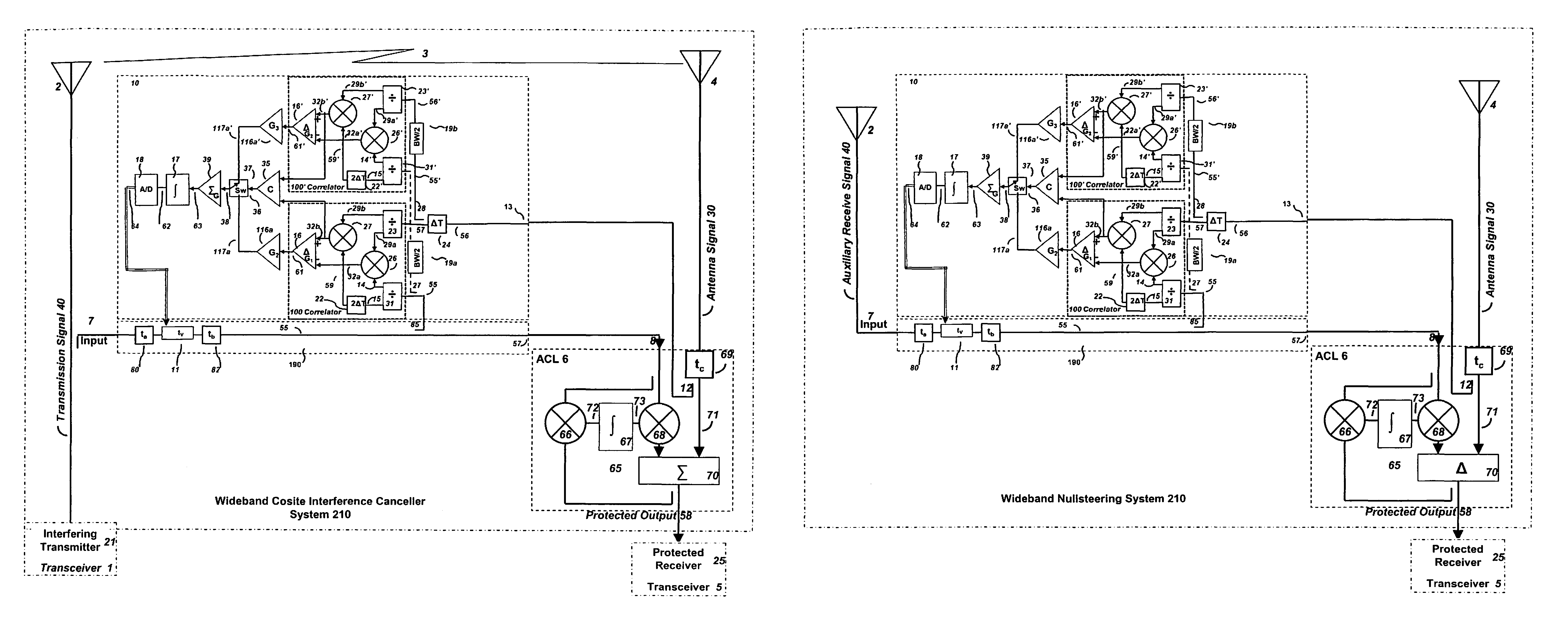
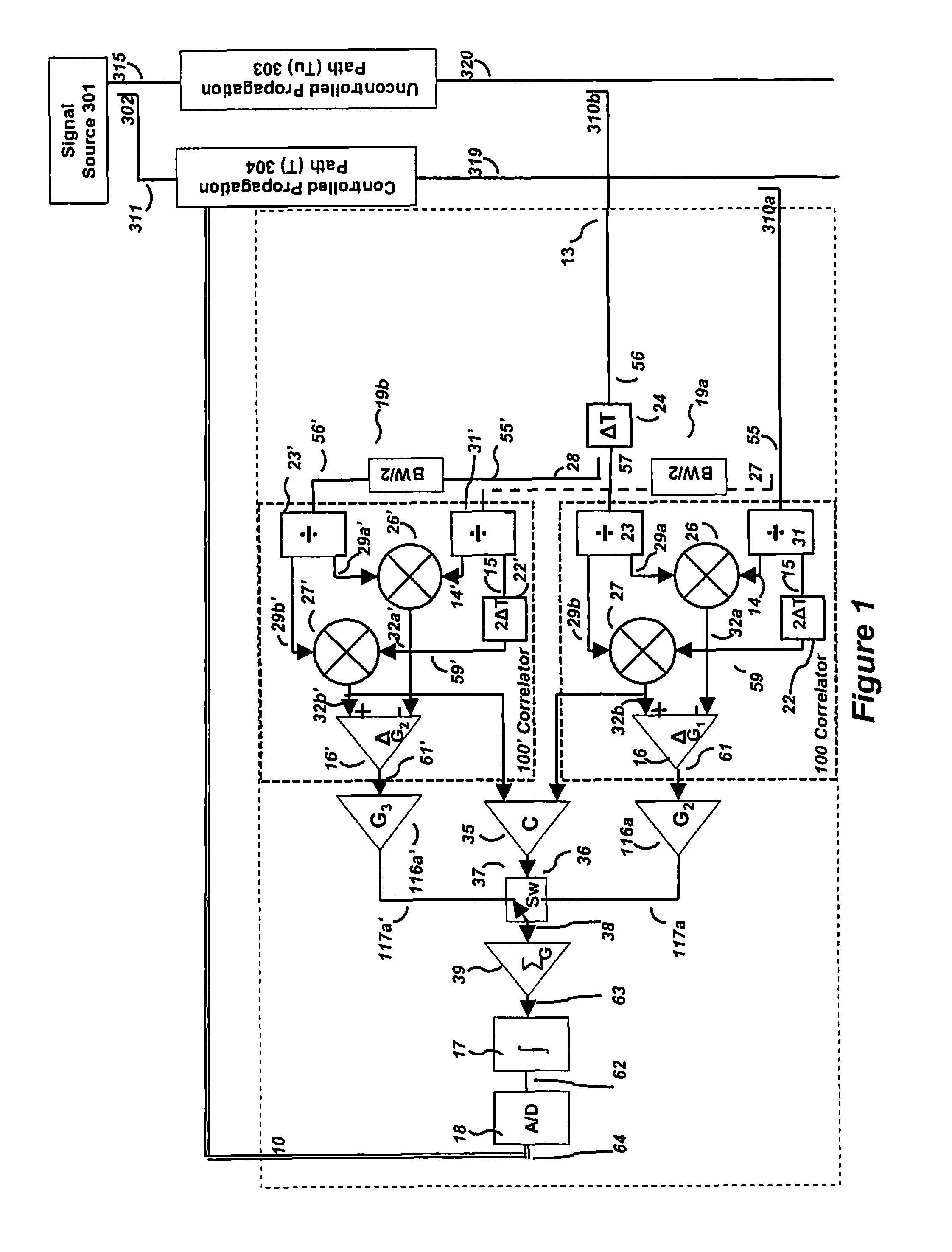
[0026]The disclosure is applicable for use, for example, in a wideband beamforming process with improved broadband gain and reduced waveform distortion. The disclosure is also applicable for use in a cosite interference cancellation system configured to provide improved rejection of a signal coupled from a transmission antenna into a local receive antenna in the presence of local multipath. The cosite interference cancellation system and associated method advantageously provide improved signal rejection over prior art approaches by continuously controlling (adjusting) a matching time delay, over a larger range than previously possible, to reduce cosite interference.

Problems solved by technology

Such prior art systems were limited to the adjustment interval due to the system bandwidth, which limits the range of scenarios in which it is operational.
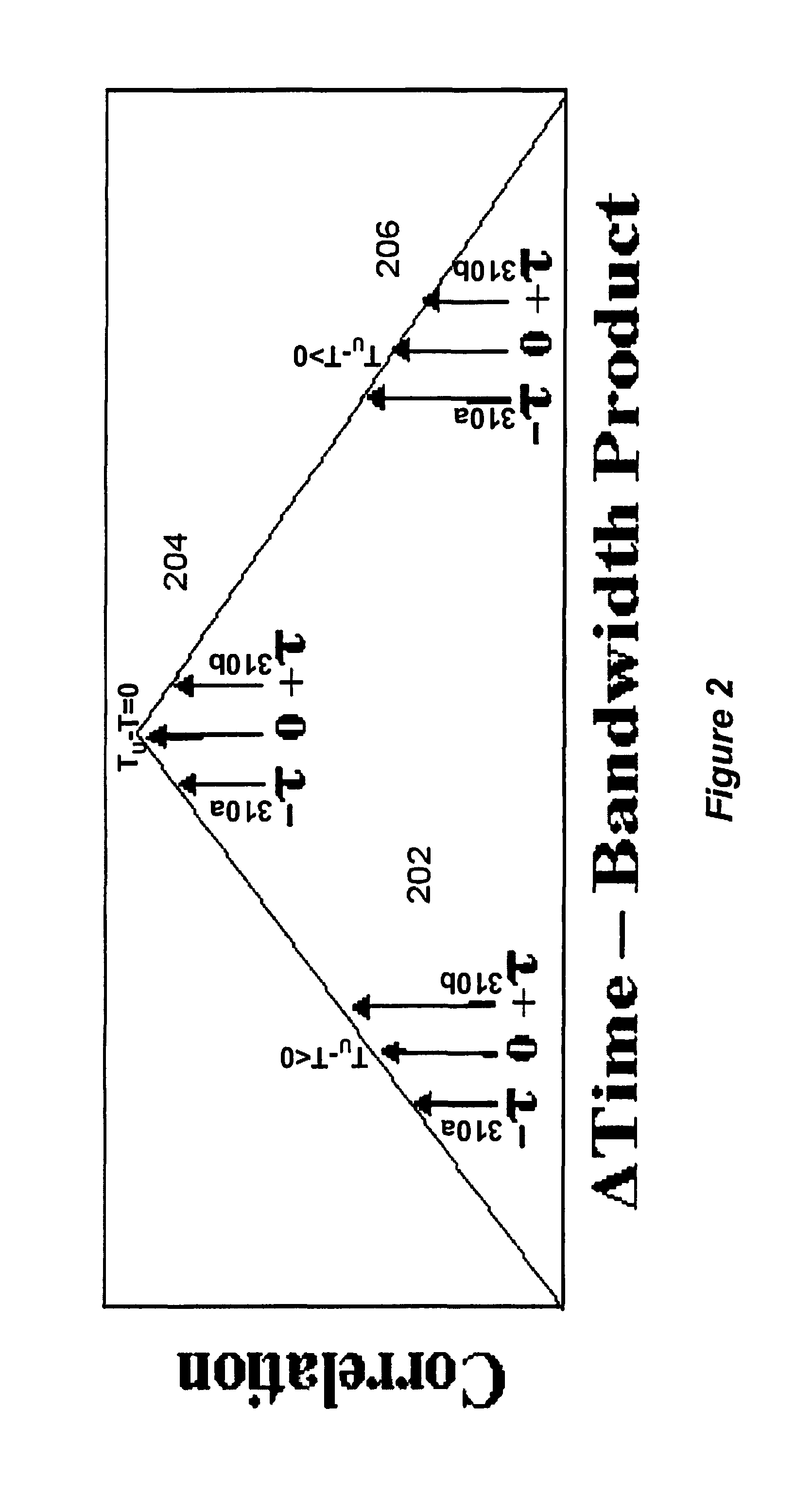
But, it's very sensitivity limits its range of operation such that it can hang up far from the point of matched delay and never find the proper solution due to non-monotonic function beyond the time interval of ±1 / BW.
As signal bandwidths become wider, the channel matching in signal processing paths requiring joint processing becomes more critical and difficult to manufacture and maintain reliably, at low cost.
In the beamforming system, the propagation of the desired signal across a large array can cause significant phase dispersion across the bandwidth of the signal.
A beamsteering system is limited in its processing bandwidth and beamsteering range by the placement of elements yielding decorrelation of the desired signal across the array.
In practice, however, the two signals have not only a phase and amplitude difference, but also a time delay yielding phase dispersion across the band, due to unwanted distortion in the propagation path length and multipath.
Each of these manifestations of interference limits the communication capabilities of the radio system afflicted by this problem.
The effects of interference can be some combination of the absence of usable output from a receiver, false signals from a receiver, and malfunction of a device which is operated by the receiver.
During emergency situations, the loss and corruption of the desired signal can be critical.
One of the greatest limitations of the nulling of this interference is the decorrelation of the interfering signal from a sample used for subtraction.
In practice, however, the two signals are not identical, due to unwanted distortion in the reference path, as well as differences in signal path lengths and non-ideal components in the Tx / Rx signal paths.
This solution is deficient to the extent that it only provides an approximate solution for a stationary environment and requires manual intervention.
Conventional manual methods do not lend themselves to situations where the time match may change over the course of time as a result of a changing environment.
Thus, a conventional interference cancellation system may suffer a loss of suppression performance due to system dynamics.
However, the taps only cover a discrete set of time-delays resulting in less than optimal results.
This solution is deficient by requiring both system interruption and manual intervention.
However, it is limited to a time delay adjustment range of ±1 / BW of the signal of interest, which limits the variability of scenarios in which it can work without manual intervention.

Method used


Image

  • Control interval expansion of variable time delay control structure for channel matching
  • Control interval expansion of variable time delay control structure for channel matching
  • Control interval expansion of variable time delay control structure for channel matching

Examples


Embodiment Construction

[0039]In the following discussion, numerous specific details are set forth to provide a thorough understanding of the present disclosure. However, those skilled in the art will appreciate that the present disclosure may be practiced without such specific details. In other instances, well-known elements have been illustrated in schematic or block diagram form in order not to obscure the present disclosure in unnecessary detail. Additionally, for the most part, details concerning network communications, electromagnetic signaling techniques, and the like, have been omitted inasmuch as such details are not considered necessary to obtain a complete understanding of the present disclosure and are considered to be within the understanding of persons of ordinary skill in the relevant art.

[0040]The present description illustrates the principles of the present disclosure. It will thus be appreciated that those skilled in the art will be able to devise various arrangements that, although not e...


PUM


Abstract

An adaptive time delay control system is provided for matching the propagation time delay between two samples of a signal traveling through two independent paths so that they can be coherently combined for additional signal processing functions such as cosite interference cancellers, adaptive interference cancellers and adaptive beam formers. The adaptive time delay control system and associated method advantageously provide improved continuous matching of the two channels over a wider adjustment range while preserving both convergence speed over the full range and minimum jitter upon convergence by using composite autocorrelation functions to control (adjusting) a matching time delay in one channel.

Description

[0001]The invention was made with United States Government support under Contract No. N00014-10-D-0162 awarded by the U.S. Navy. The United States Government has certain rights in this invention.BACKGROUND OF THE DISCLOSURE[0002]1. Field of the Disclosure[0003]The disclosure relates generally to the field of radio communication and, in particular, to time delay adjustment control to match different signal paths to a common delay to aid further signal processing in applications such as coherent combining, wideband beam-forming, and wideband signal cancellation including the reduction of interference signals coupled from a transmission antenna into a local receive antenna in the presence of a local multipath.[0004]2. Description of the Related Art[0005]The prior art has demonstrated that an autocorrelation result between the transmitted reference signal and the continuously varied time-delayed version is indirectly proportional to the time-bandwidth product of the two multiplied signa...

Claims


Application Information

Patent Timeline
Patent Type & Authority Patents(United States)
IPC IPC(8): H04B7/10H04L1/02
CPCH04B7/0837H04B7/0671
Inventor LACKEY, RAYMOND J.
Owner BAE SYST INFORMATION & ELECTRONICS SYST INTERGRATION INC
Learn More