
Nickel-based reforming catalysts

a technology of reforming catalysts and nickel-based materials, which is applied in the direction of physical/chemical process catalysts, bulk chemical production, and other chemical processes, can solve the problems of shortening the catalyst life, affecting the stability of the catalyst, so as to prolong the catalyst life, and improve the stability of the pore structur

Inactive Publication Date: 2013-11-05
HE HONGYING
View PDF18 Cites 18 Cited by
  • Summary
  • Abstract
  • Description
  • Claims
  • Application Information

AI Technical Summary

Benefits of technology

The catalysts exhibit improved stability and prolonged life by preventing nickel sintering and electrolyte deposition, maintaining catalytic activity and extending the operational lifespan of molten carbonate fuel cells.

Problems solved by technology

During power generation, internal electrical resistance in molten carbonate fuel cells generates undesirable heat.
There are difficulties in the direct internal reforming of hydrocarbons for molten carbonate fuel cells that arise from the contamination of reforming catalysts via constant diffusion and deposition of the electrolyte vapors of Li—Na—K hydroxide(s) and / or carbonate(s).
This electrolyte deposition continuously deactivates the reforming catalysts throughout the life of catalyst usage, which results in a shortened catalyst life.
Losing the surface area of the active components leads to the loss of the catalytic activity of hydrocarbon reforming, which also results in a shortened catalyst life.
Reforming catalysts are usually sensitive to the deposition of sulfur-related chemicals, which leads to the deactivation of the reforming catalysts.
Sulfur poisoning from the hydrocarbon feeds can also result in a shortened catalyst life.
A combination of deactivations caused by the presence of heat, the presence of steam, and the deposition of electrolytes causes reforming catalysts to lose their capacity for activity until eventually, they are no longer efficient enough to allow the fuel cells to function normally.
Extending the life of reforming catalysts is a key challenge in the development of molten carbonate fuel cells with prolonged operational lifespan.

Method used


Image

  • Nickel-based reforming catalysts
  • Nickel-based reforming catalysts
  • Nickel-based reforming catalysts

Examples


example 1

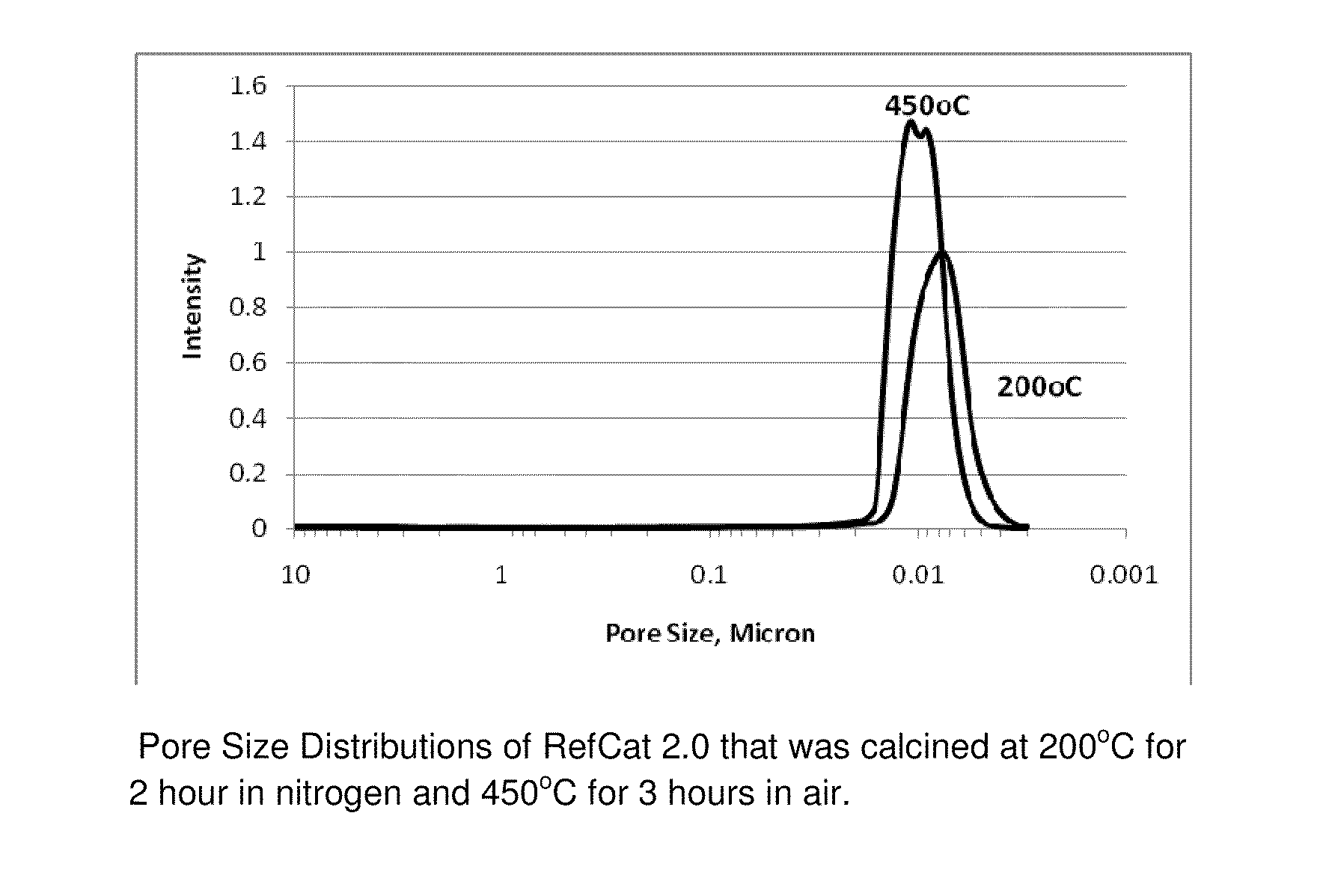
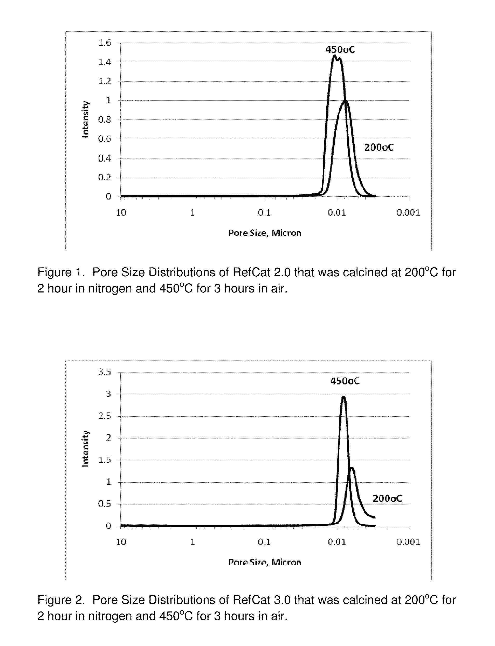
RefCat 2.0 Containing Ni and Al

[0082]The nickel carbonate powders containing 46% Ni (15.2 g) were dispersed in 148 grams of water under stirring conditions in a 400 mL beaker. Then, 16.3 grams of acetic acid were added into the nickel carbonate slurry. The slurry was then heated to dissolve nickel carbonate, evolving carbon dioxide gas until the solution of nickel acetate became clear. The obtained nickel acetate solution was cooled down to room temperature and became Solution I.

[0083]Subsequently, 5.5 grams of baking soda (NaHCO3) powder were weighed into a 1000 mL beaker. Then, 359 grams of water were added into this 1000 mL beaker. Under mixing conditions, 16.5 grams of caustic soda (50% NaOH) were then added into the baking soda solution. Next, 14.99 grams of sodium aluminate solution (20.2% alumina), SAX-19 from Kemira, were added into the above 1000 mL beaker containing a solution of NaHCO3 and NaOH, under mixing conditions. The resulting solution became Solution II.

[0084]Unde...

example 2

RefCat 3.0 Containing Ni, Al, and Zr

[0085]The nickel carbonate powders containing 46% Ni (14.06 g) were dispersed in 138 grams of water under stirring conditions in a 400 mL beaker. Then, 15.2 grams of acetic acid were added into the nickel carbonate slurry. The slurry was then heated to dissolve nickel carbonate, evolving carbon dioxide gas until the solution of nickel acetate became clear. The obtained nickel acetate solution was cooled down to room temperatures and became Solution I.

[0086]In a 100 mL beaker, 2.8 grams of acetic acid were mixed into 9.6 grams water under mixing conditions. Then, 4.7 grams of ammonium zirconium carbonate (20% zirconia) were dripped into the acetic solution under mixing. It was observed that carbon dioxide gas evolved out of the solution. After the reactions were complete, the pH of the solution containing zirconium was measured to be about 5.0. This clear solution containing zirconium was then dripped into Solution I under mixing conditions. The cl...

example 3

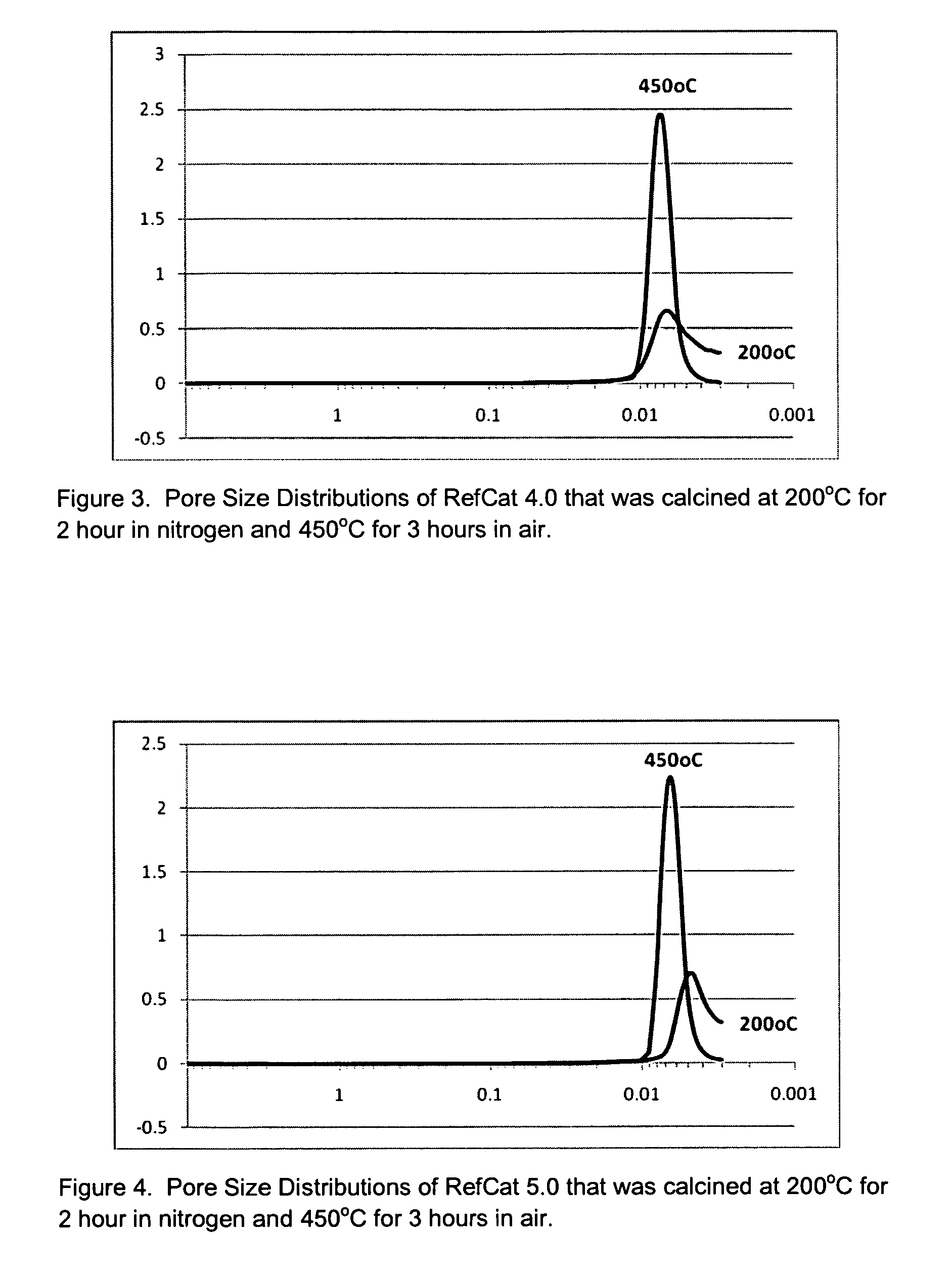
RefCat 4.0 Containing Ni, Al, Zr, and Ce

[0089]The powders of nickel carbonate containing 46% Ni (13.75 g) were dispersed in 134.6 grams of water under stirring conditions in a 400 mL beaker. Then 15.0 grams of acetic acid were added into the nickel carbonate slurry. The slurry was then heated to dissolve nickel carbonate, evolving carbon dioxide until the solution of nickel acetate became clear. The obtained nickel acetate solution was cooled down to room temperatures and became Solution I.

[0090]In a 100 mL beaker, 2.9 grams of acetic acid was mixed with 9.5 grams of water under mixing conditions. Then, 4.6 grams of ammonium zirconium carbonate (20% IRCONIA) was dripped into the acetic solution under mixing. It was observed that carbon dioxide gas evolved out the solution. After the reactions were complete, the pH of the solution containing zirconium was measured to be about 5.0. This clear solution containing zirconium was then dripped into Solution I under mixing. The clear soluti...


PUM

PropertyMeasurementUnit
sizeaaaaaaaaaa
sizeaaaaaaaaaa
sizeaaaaaaaaaa

Abstract

The present invention relates unique pore structures in nickel supported on alumina with the negligible formation of macropores. Incorporation of additional elements stabilizes the pore structure of the nickel supported on alumina. Additional element(s) were then further added into the nickel-supported materials. These additional element(s) further stabilize the pore structures under heating conditions. The improvements of pore structure stability under heating conditions and negligible presence of macropores limit the sintering of nickel metal to a mechanism of impeded diffusion. The negligible presence of macropores also limits the deposition of alkali metal hydroxide(s) / carbonate(s) on the outer shell of the catalyst pellet in the molten carbonate fuel cells. Both the negligible presence of macropores and improvement in pore structure stability allow for prolonging the catalyst life of these nickel supported on alumina catalysts of the present invention for reforming hydrocarbons.

Description

CROSS-REFERENCE TO PRIOR RELATED APPLICATION[0001]This application claims benefit of the filing date of U.S. Provisional Application No. 61 / 108,562, filed on Oct. 27, 2008, the entire disclosure of which is incorporated herein by reference.FIELD OF THE INVENTION[0002]This invention relates to the chemical compositions and pore structures of nickel-based materials that are used as catalysts for the catalytic reforming of hydrocarbons. More particularly, this invention relates to nickel-based reforming catalysts and their favorable pore structures for the reforming of hydrocarbons to produce syngas. Furthermore, the invented nickel based catalysts have unique compositions and pore structures that facilitate a long catalyst life for syngas production (for fuel cells or other applications) under conditions of heat, steam, and electrolyte deposition.BACKGROUND OF THE INVENTION[0003]The reforming of hydrocarbons to produce a mixture of hydrogen, carbon monoxide, carbon dioxide, hydrocarbo...

Claims


Application Information

Patent Timeline
Patent Type & Authority Patents(United States)
IPC IPC(8): B01J23/00B01J21/00
CPCB01J23/755B01J23/78B01J23/83B01J23/835B01J23/8435B01J23/8437B01J23/8474B01J23/883B01J23/888B01J35/1061B01J35/1066B01J35/108B01J35/109B01J37/031C01B3/40B01J37/04C01B2203/0227C01B2203/1058Y02P20/52B01J35/651B01J35/66B01J35/69B01J35/647
Inventor XU, WEN-QINGXU, DAVID BEIJIA
Owner HE HONGYING
Learn More