Optical cytometry
a cytometric and optical technology, applied in the field of optical cytometry, can solve the problems of low degree and significance of mechanical anisotropy and its population variance, existing cytometric approaches, and high-magnification particle tracking microrheology
- Summary
- Abstract
- Description
- Claims
- Application Information
AI Technical Summary
Benefits of technology
Problems solved by technology
Method used
Image
Examples
example 1
High-Throughput Cell Nano-Mechanics with Mechanical Imaging Interferometry
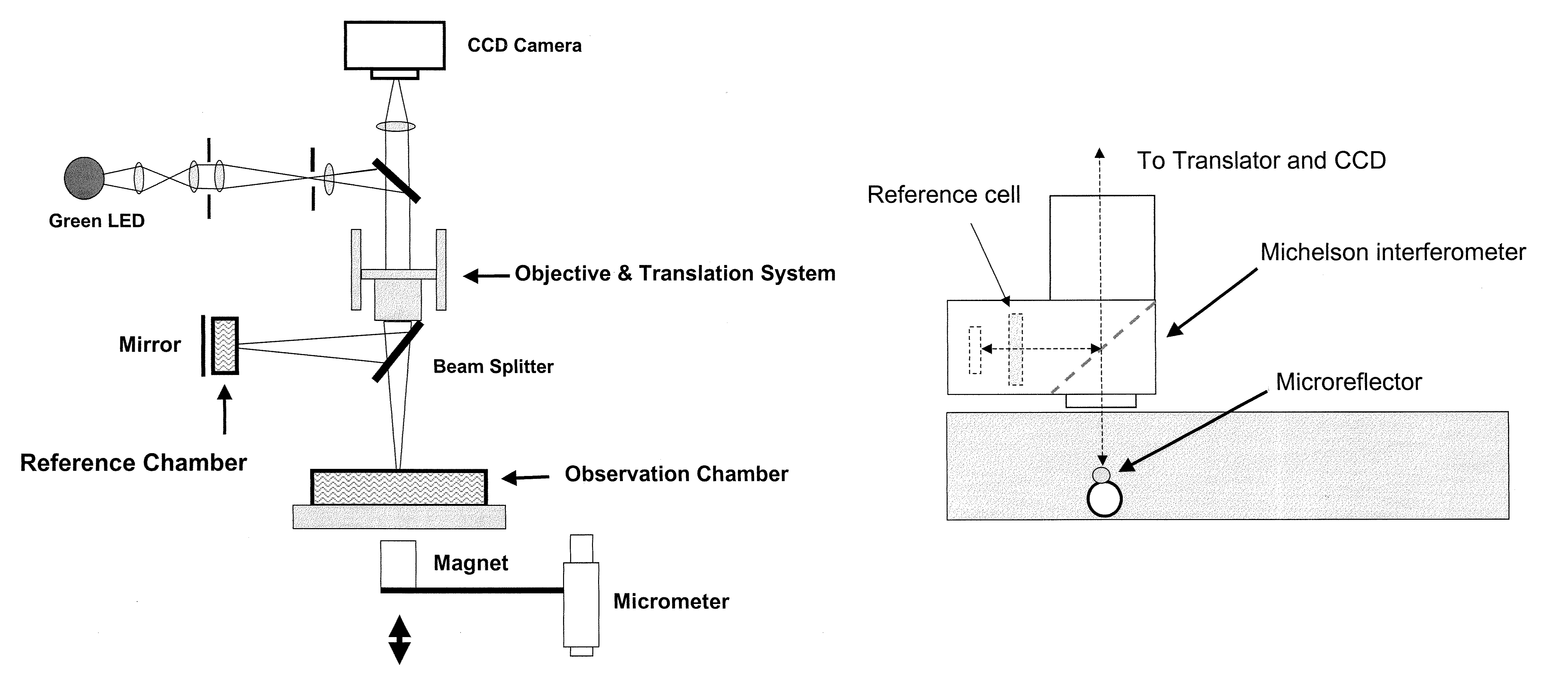
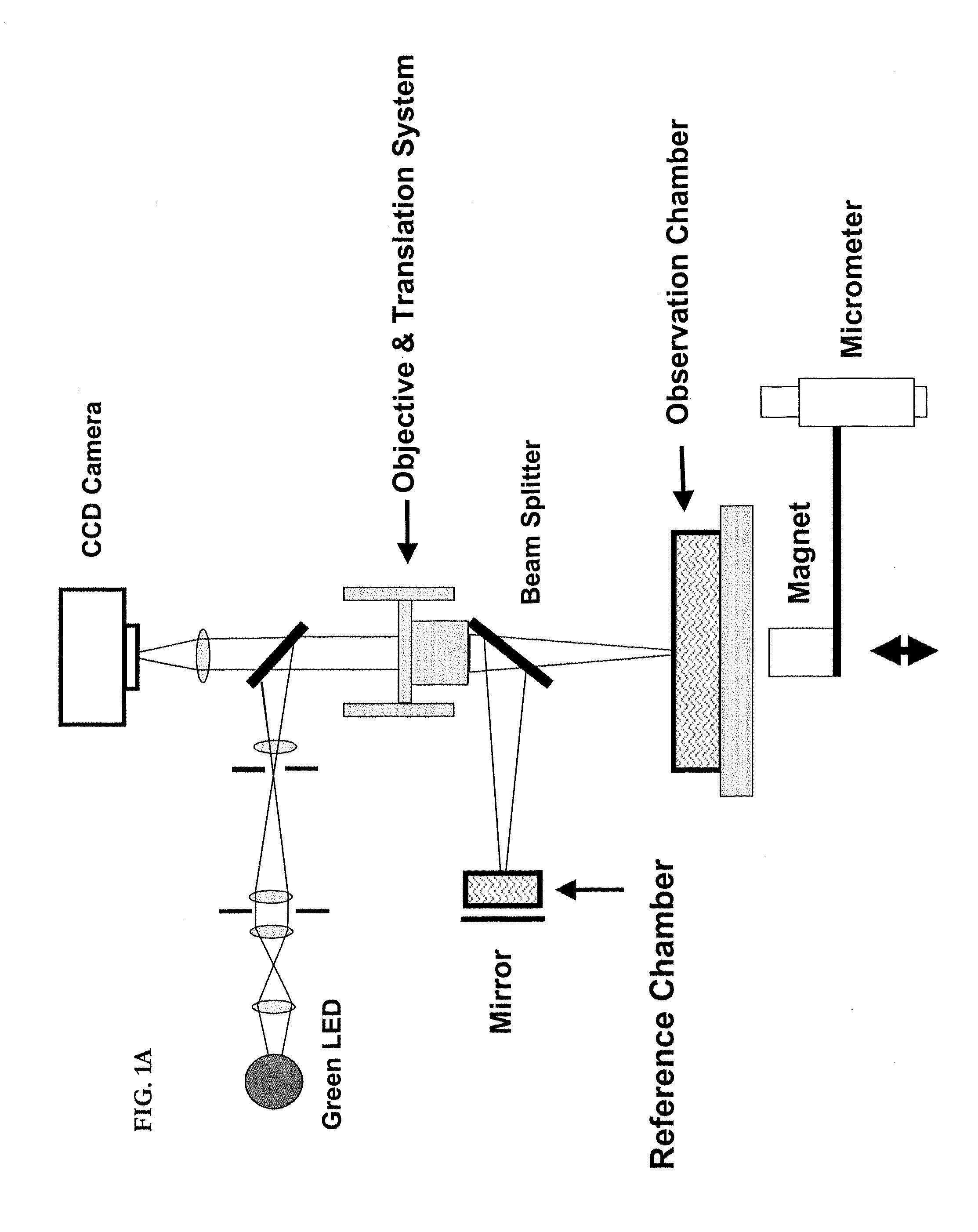
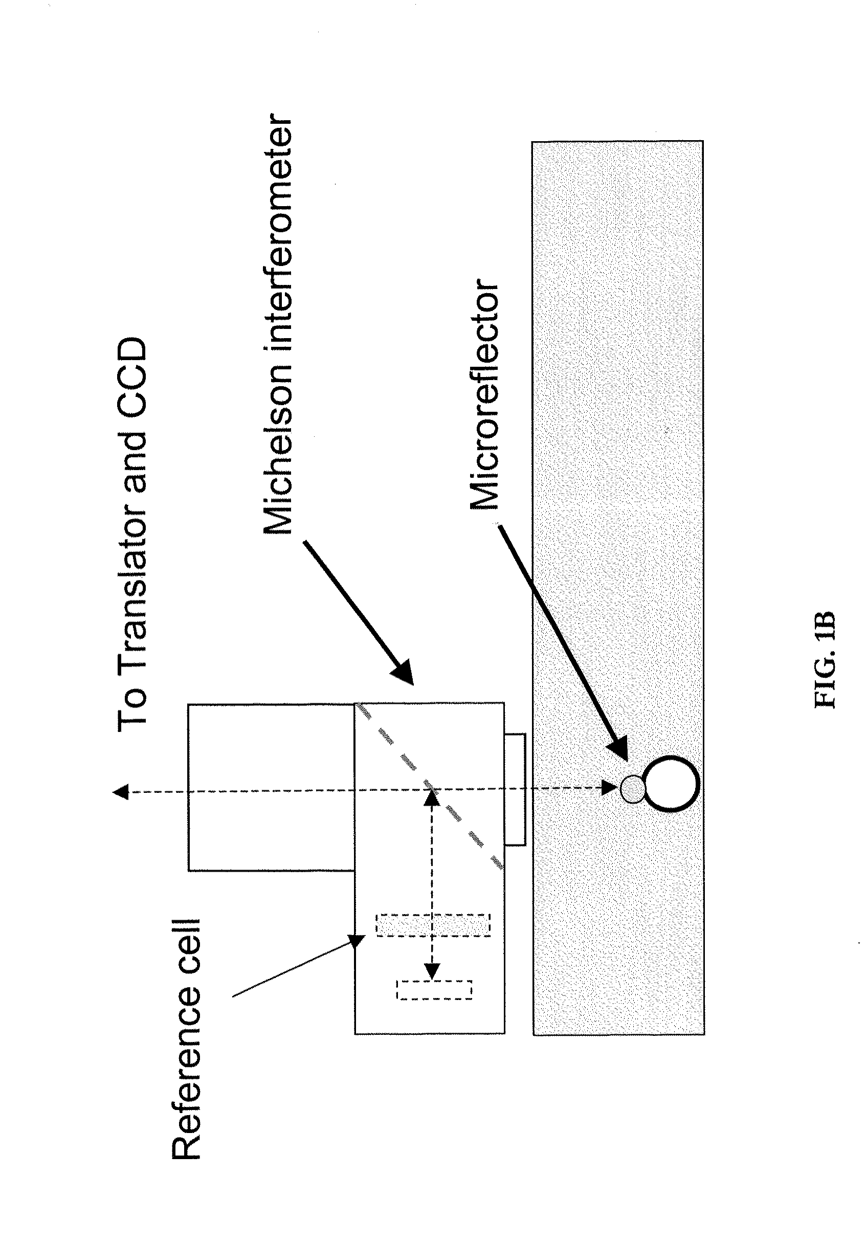
[0135]This example provides an illustrative, high-throughput approach to measuring the nano-mechanical properties of a large number of cells in parallel, based on imaging interferometry in combination with reflective, magnetic probes attached to cells. In this example, we measure local elastic properties with applied forces of 20 pN to 20 nN, a spatial resolution of <20 nm, and a mechanical dynamic range of several Pa up to ˜200 kPa. This disclosure provides evidence that mechanical imaging interferometry (MII) is a sensitive and scalable technology for measuring the nanomechanical properties of large arrays live cells in fluid. Illustrative data for NIH 3T3 and HEK 293T fibroblasts as well as the effects of actin depolymerizing drugs are disclosed.
[0136]This example demonstrates a nanomechanical probing method, called mechanical imaging interferometry (MII), based on combining vertical scanning interferometry...
example 2
Live Cell Interferometry Reveals Cellular Dynamism During Force Propagation
[0166]This example provides an illustration of how to employ live-cell-interferometry (LCI) to visualize the rapid response of a whole cell to mechanical stimulation, on a time scale of seconds, and we detect cytoskeletal remodeling behavior within 200 seconds. This behavior involved small, rapid changes in cell content and miniscule changes in shape; it would be difficult to detect with conventional or phase contrast microscopy alone, and is beyond the dynamic capability of AFM. We demonstrate that LCI provides a rapid, quantitative reconstruction of the cell body with no labeling, which is highly complementary to traditional microscopy and flow cytometry, which require cell surface marker detection and / or destructive cell fixation for labeling.
[0167]Briefly, mammalian cells exhibit continuous regional motion and shape changes controlled by a dynamic cytoskeleton. The movements of a cell are orchestrated by ...
example 3
Grin Spherical Mirror: A General Optical Probe Useful with Embodiments of the Invention
[0184]A wide variety of micromirrors can be used with embodiments of the invention, including for example commercially available micron-sized elemental nickel microspheres and the like. In addition, one can use a gradient index (GRIN) retro reflector device with very wide viewing angle and high reflectivity. While not confined to uses with interferometry, these micromirror embodiments can make an ideal probe for very accurate interferometric measurements. In addition, while typically a micromirror, the GRIN mirror can be of any size, down to nanometers in diameter.
[0185]Such GRIN mirrors can be manufactured to have a variety of properties which allow them to be used in a variety of contexts. For example, these optical probes can be sensitive to magnetic, electric and gravitational fields. Such probes can be used for example: (1) to sense seismic waves or gravity waves; (2) as a metrology device fo...
PUM
| Property | Measurement | Unit |
|---|---|---|
| diameter | aaaaa | aaaaa |
| diameter | aaaaa | aaaaa |
| diameter | aaaaa | aaaaa |
Abstract
Description
Claims
Application Information
 - R&D
- Intellectual Property
- Life Sciences
- Materials
- Tech Scout
- Unparalleled Data Quality
- Higher Quality Content
- 60% Fewer Hallucinations
Browse by: Latest US Patents, China's latest patents, Technical Efficacy Thesaurus, Application Domain, Technology Topic, Popular Technical Reports.
© 2025 PatSnap. All rights reserved.Legal|Privacy policy|Modern Slavery Act Transparency Statement|Sitemap|About US| Contact US: help@patsnap.com


