

Composite crystal colloidal array with photochromic member
a colloidal array and composite material technology, applied in the field of composite materials, can solve the problems of relatively limited use of radiation diffracting materials in security devices
- Summary
- Abstract
- Description
- Claims
- Application Information
AI Technical Summary
Benefits of technology
Problems solved by technology
Method used
Image

Examples
example 1
Step 1: UV Curable Organic Matrix
[0163]An ultraviolet radiation curable organic composition was prepared via the following procedure. Diphenyl(2,4,6-trimethylbenzoyl) phosphineoxide / 2-hydroxy-2-methyl-propiophenone (0.25 g), 50 / 50 blend from Aldrich Chemical Company, Inc., Milwaukee, Wis., was added with stirring to a mixture of 6 g ethoxylated (20) trimethylol propane triacrylate and 3.5 g of propoxylated neopentyl glycol diacrylate, and 0.5 g of pentaerythritol tetraacrylate, all from Sartomer Company, Inc., Exton, Pa.
Step 2: Color-Shifting, Imaged Crystalline Colloidal Array Film
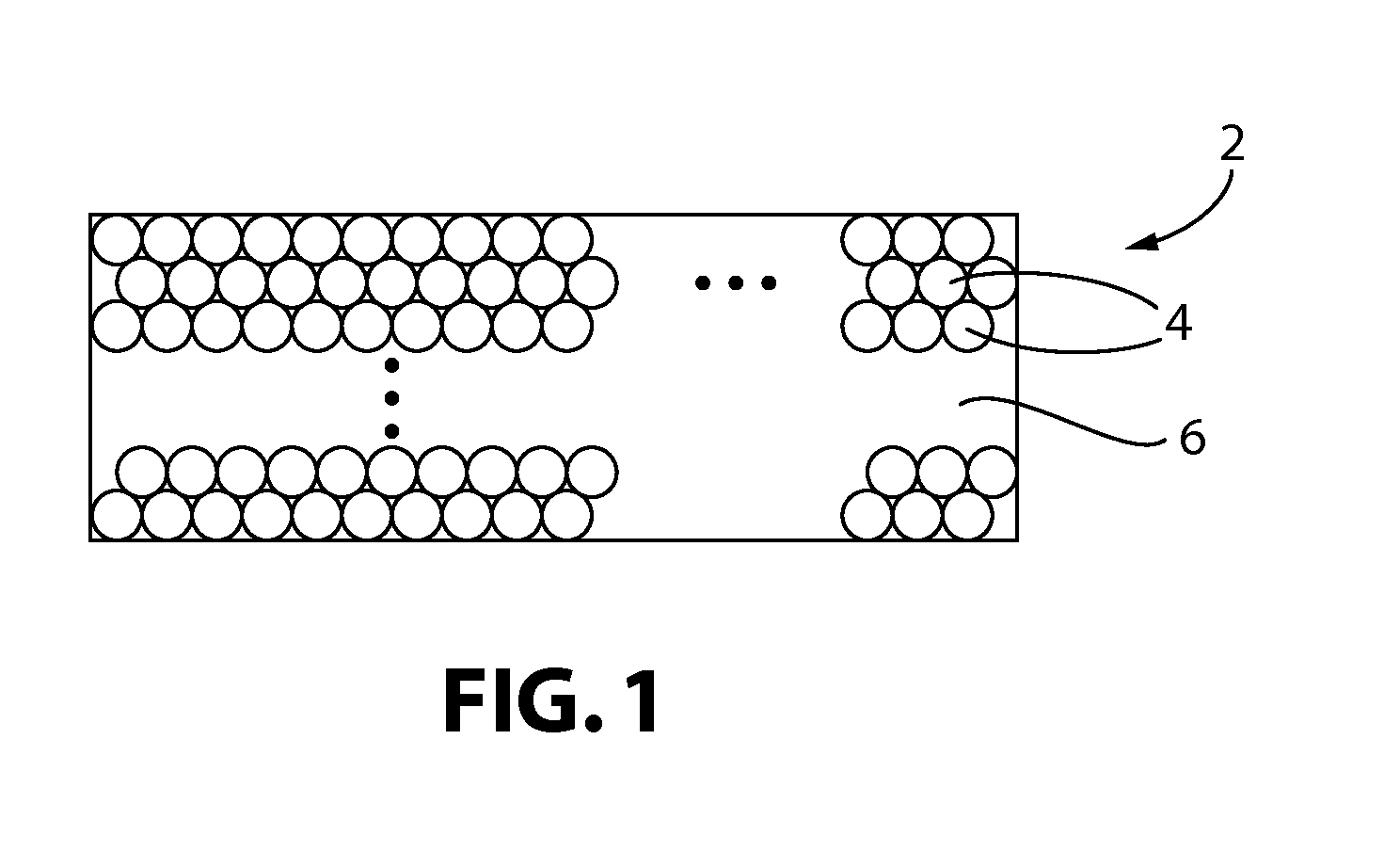
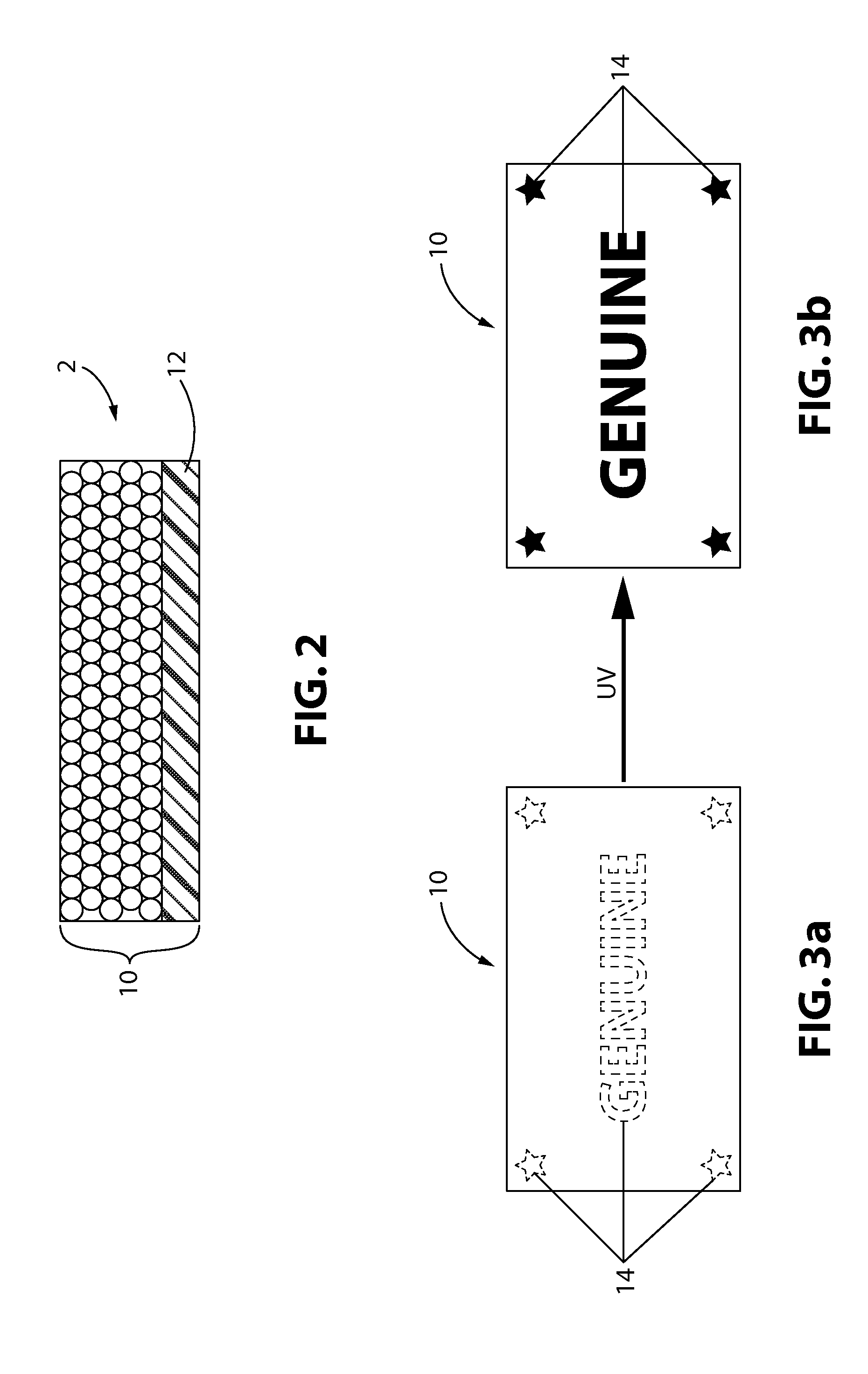
[0164]A crystalline colloidal array (CCA) film without the interstitial spaces filled was prepared in the same manner as described in U.S. Pat. No. 7,682,530 on a polyethylene terephthalate (PET) support film. Material from Step 1 of Example 1 was applied to this film to fill the interstitial spaces. A PET coversheet was applied over the film and UV radiation curable coating was then rolled to spread the ...
example 2
Step 1: UV Radiation Curable Organic Matrix Containing Photochromic Dye
[0167]A gray photochromic dye composition was prepared using the crystalline organic dyes PPG Photosol® 0265, PPG Photosol® 5-3, PPG Photosol® 7-106, commercially available from PPG Industries, Inc., Pittsburgh, Pa. The dyes were each added at 0.33 g to 3 g of methyl ethyl ketone to make a homogeneous mixture. The solvent and dye mixture was added to 6 g of the UV radiation curable organic composition from Example 1 in an open container. The container was placed in a 200° F. oven for approximately 1 hour to evaporate the 3 g methyl ethyl ketone. A material balance was used to determine the elimination of methyl ethyl ketone.
Step 2: Color-Shifting, Imaged Crystalline Colloidal Array Film Containing Photochromic Dye
[0168]A CCA film without the interstitial spaces filled was prepared in the same manner as described in U.S. Pat. No. 7,682,530 on a PET support film. Material from Step 1 of Example 2 was applied to thi...
example 3
Step 1: Color-Shifting, Imaged Crystalline Colloidal Array Film on a Support
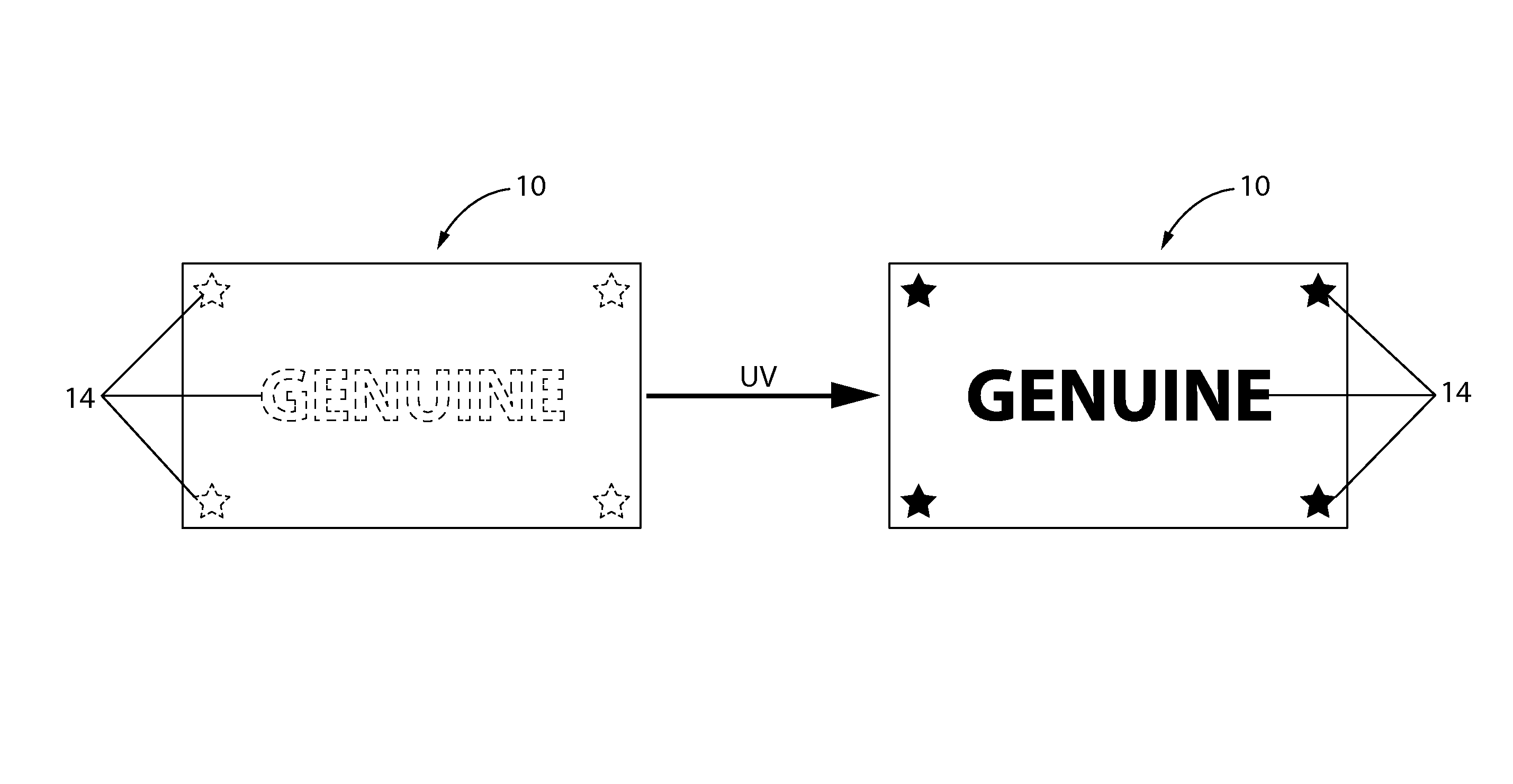
[0171]A CCA film without the interstitial spaces filled was prepared in the same manner as described in U.S. Pat. No. 7,682,530 on a PET support film. Material from Step 1 of Example 1 was applied to this film to fill the interstitial spaces. A PET coversheet was applied over the film and UV radiation curable coating and was then rolled to spread the UV radiation curable coating to a uniform thickness. The film was heated in a 215° F. oven until a color change was observed when looking at the film from a normal angle (green to orange reflectance), then placed on an opacity chart (byko-chart, BYK-Gardner USA) with the PET coversheet facing the black background. An image of a simple shape was printed with an ink jet printer onto a transparency to create a mask. The mask was placed on the backside of the PET substrate supporting the CCA film and the assembly was exposed to UV radiation. The mask was removed and...
PUM
| Property | Measurement | Unit |
|---|---|---|
| wavelength | aaaaa | aaaaa |
| wavelength | aaaaa | aaaaa |
| thickness | aaaaa | aaaaa |
Abstract
Description
Claims
Application Information