Linear motor with permanent-magnetic self-holding

a permanent magnet, linear motor technology, applied in the direction of electric controllers, instruments, ignition automatic control, etc., can solve the problems of linear drive sluggishness, inability to adjust the focal length of the lens, rigid system and limited optical quality, etc., to reduce static friction or sliding friction in the interior of the motor, and reduce static and sliding friction. friction

Active Publication Date: 2014-02-04
KARL STORZ GMBH & CO KG
View PDF28 Cites 14 Cited by
  • Summary
  • Abstract
  • Description
  • Claims
  • Application Information

AI Technical Summary

Benefits of technology

[0008]It is the object of the invention to provide a linear motor having such small dimensions that this can be inserted in endoscopes. Furthermore, the linear motor should have a defined zero point position and a reproducible deflection as a function of the control signal. In addition, the linear motor should exhibit large driving forces with small mass and thereby render possible a rapid, continuous and exact positioning of the optical system in the largest possible range. At the same time, the beam path through the optical system must not be blocked during displacement of the components. The power loss of the linear motor should be low so that little heat is produced in the tip of an endoscope. The drive should be composed of as few as possible and as geometrically simple as possible individual components for simple manufacture and assembly.
[0018]The linear motor can easily be miniaturized as far as a size of a few millimeters external diameter. In a motor having an external diameter of a few millimeters, the travel distance between the two end positions of the armature is typically about 1 to 3 mm.
[0021]It is particularly favorable if the coil is supplied with a direct current with a superposed alternating current of small amplitude and having a frequency up to a maximum of 1 kHz. The static and sliding friction can be reduced by this means.
[0022]A further embodiment is a method for operating a linear motor, wherein the linear motor is supplied with a direct current and a superposed alternating current of small amplitude and having a frequency up to a maximum of 1 kHz. The static friction or sliding friction in the interior of the motor can be reduced by this means.

Problems solved by technology

As a result of the rod lenses, the system is rigid and limited in optical quality.
An adjustment of the focal length of the lens is not possible.
However, as a result of the large mass of the permanent magnet, the linear drive is sluggish.
The complex structure of the drive can be readily implemented in video cameras having lens diameters in the centimeter range but is not scalable to the size required for endoscope applications in the millimeter range.
An expensive controlling circuit is required to produce the moving field.
A disadvantage here is the dependence of the stroke and the adjusting forces on the soft-magnetic stator pole pieces, with the result that a high precision is required in the manufacture and assembly of these parts.

Method used


Image

  • Linear motor with permanent-magnetic self-holding
  • Linear motor with permanent-magnetic self-holding
  • Linear motor with permanent-magnetic self-holding

Examples


Embodiment Construction

[0036]While the invention is susceptible to various modifications and alternative forms, specific embodiments thereof are shown by way of example in the drawings and will herein be described in detail. It should be understood, however, that the drawings and detailed description thereto are not intended to limit the invention to the particular form disclosed, but on the contrary, the intention is to cover all modifications, equivalents and alternatives falling within the spirit and scope of the present invention as defined by the appended claims.

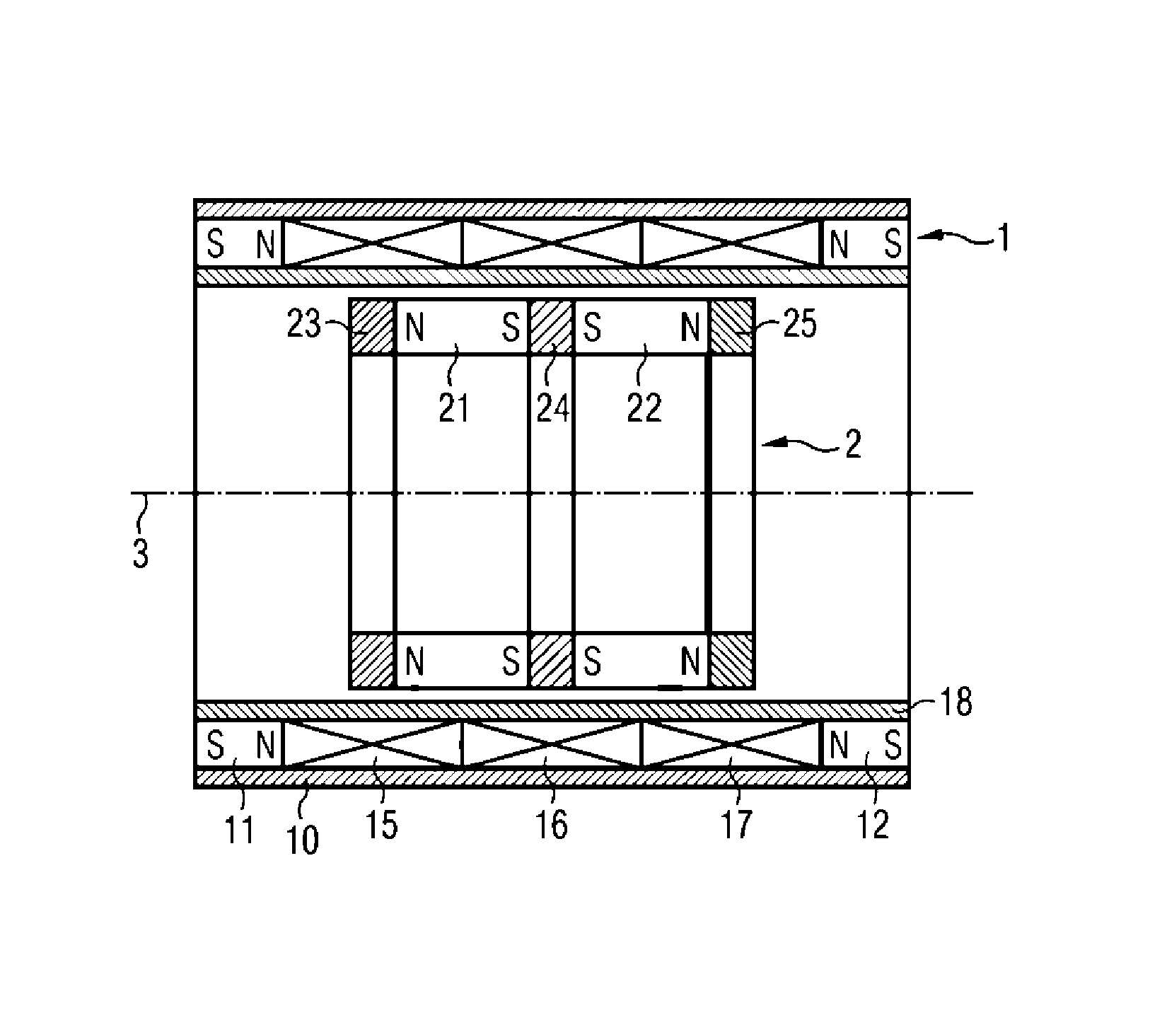
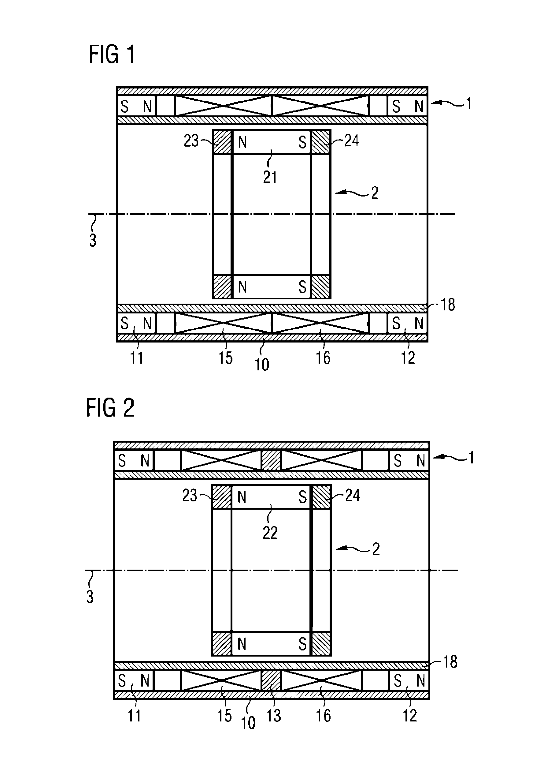
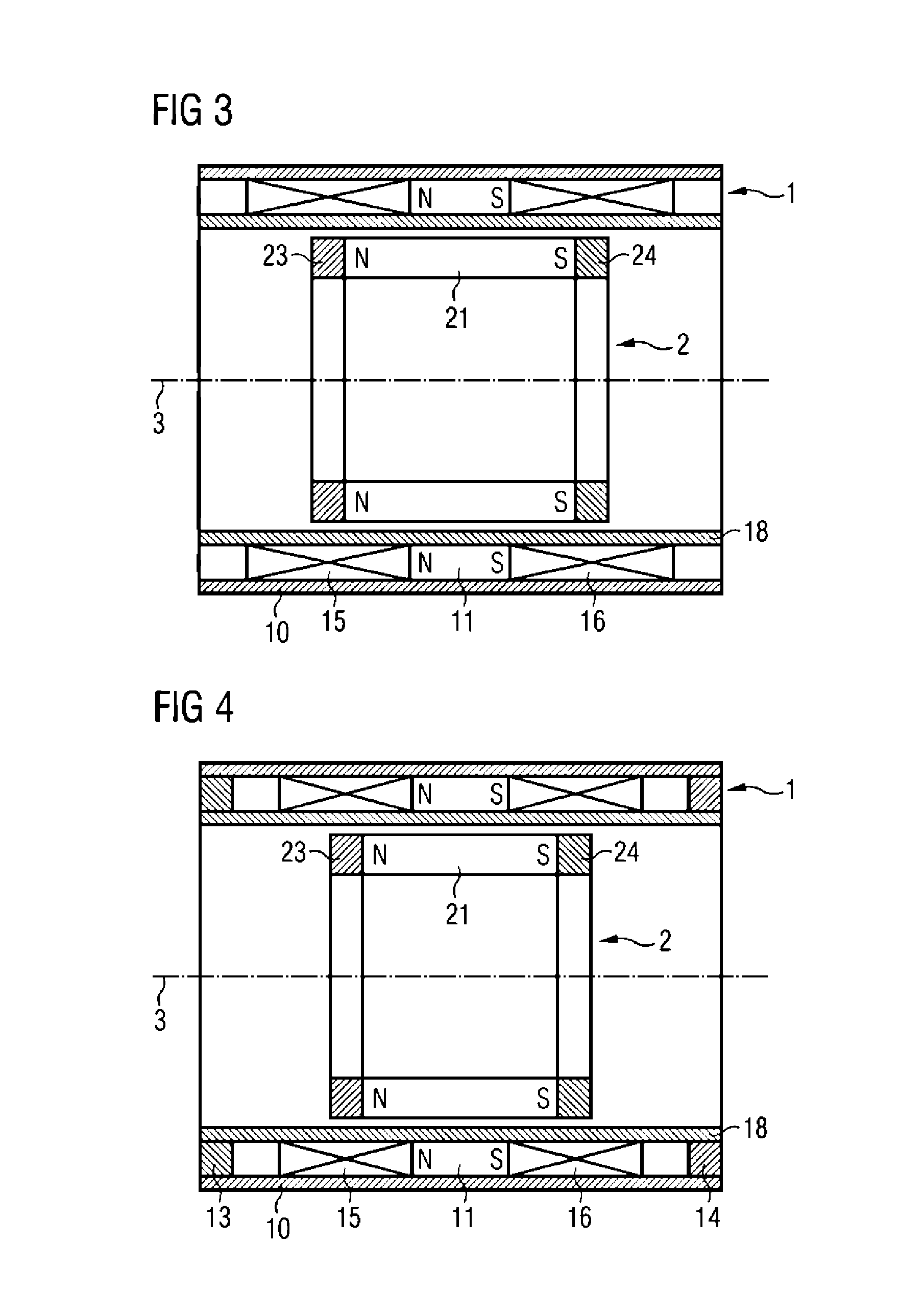
[0037]FIG. 1 shows schematically an exemplary embodiment of an arrangement in cylindrical design in sectional view. The stator 1 comprises a magnetic guiding member 10 in the form of a soft-magnetic tube, a first coil 15 and a second coil 16 being disposed in the bore whereof. Neighboring coils each have current flowing therethrough in opposite directions. A first permanent magnet 11 is disposed on one side of the coils. A second permanent ma...


PUM


Abstract

A linear motor for optical systems, for example, endoscopes, is described. The motor has a stator with a magnetic guiding member and two adjacently disposed coils which are energized in opposite directions. Furthermore permanent magnets polarized in opposite directions and in the axial direction are provided on both sides of the pair of coils. The armature of the motor has a permanent magnet which is polarized in the opposite direction to the permanent magnet of the stator and is connected to a pole piece at each end. The pole pieces are arranged so that in the rest position each pole piece lies at the centre of one of the coils. By applying current to the coil, the armature can be displaced from a rest position in the longitudinal direction.

Description

CROSS-REFERENCE TO RELATED APPLICATIONS[0001]The present application claims priority German patent application No. 10 2010 000 582.7 filed on Feb. 26, 2010.FIELD OF THE INVENTION[0002]The invention relates to a linear motor in particular for optical systems. Such optical systems are used, for example, in endoscopes. In modern video endoscopes a camera chip and an appurtenant lens system are integrated in the endoscope tip. A miniaturized motor is required to adjust the focal length or the focus of the lens system.BACKGROUND OF THE INVENTION[0003]Classical endoscopes such as can be used, for example, for minimally invasive surgery, guide the image by means of rod lenses from the intracorporeal objective to the extracorporeal eyepiece. As a result of the rod lenses, the system is rigid and limited in optical quality. Modern video endoscopes use a camera chip in the endoscope tip. Such an endoscope is disclosed in U.S. Pat. No. 7,365,768 B1. This has a rigidly disposed lens in front of...

Claims


Application Information

Patent Timeline
Patent Type & Authority Patents(United States)
IPC IPC(8): H02K41/00
CPCH02K1/2726H02K7/14H02K7/106H02K1/2713H02K41/031H02K7/09A61B1/00096A61B1/00188G02B7/08G02B23/2476
Inventor VOGEL, WALTER
Owner KARL STORZ GMBH & CO KG
Why Eureka
Try Eureka