Fuel combined with carbon dioxide in elongate chamber

a technology of carbon dioxide and elongate chamber, which is applied in the direction of liquid fuel feeders, machines/engines, mechanical equipment, etc., can solve the problems of reducing the efficiency of the combustion process, reducing and not being able to completely burn the fuel. , to achieve the effect of enhancing the absorption of carbon dioxide in the fuel

Inactive Publication Date: 2014-03-25
MUCCIACCIARO DOMENIC
View PDF6 Cites 1 Cited by
  • Summary
  • Abstract
  • Description
  • Claims
  • Application Information

AI Technical Summary

Benefits of technology

[0012]feeding carbon dioxide into the vessel through the carbon dioxide inlet during the process of fuel conditioning in the vessel and feeding conditioned fuel into a high-pressure fuel pump and further into the combustion chamber; to provide an extended path for the fuel and carbon dioxide for enhanced absorption of carbon dioxide in the fuel. Although the invention is illustrated and described herein as embodied in method and system for liquid fuel conditioning, it is nevertheless not intended to be limited to the details shown, since various modifications and structural changes may be made therein without departing from the spirit of the invention and within the scope and range of equivalents of the claims. The construction and method of operation of the invention, however, together with additional objects and advantages thereof will be best understood from the following description of specific embodiments when read in connection with the accompanying drawings.

Problems solved by technology

This part of fuel can not be burnt completely and may be lost in the exhaust.
Uneven distribution of the liquid fuel particles over a volume of the combustion chamber causes a delay in flame propagation, lowering the efficiency of the combustion process, thereby delivering less power.
But even those systems are not free from above mentioned shortcomings.

Method used


Image

  • Fuel combined with carbon dioxide in elongate chamber
  • Fuel combined with carbon dioxide in elongate chamber
  • Fuel combined with carbon dioxide in elongate chamber

Examples


Embodiment Construction

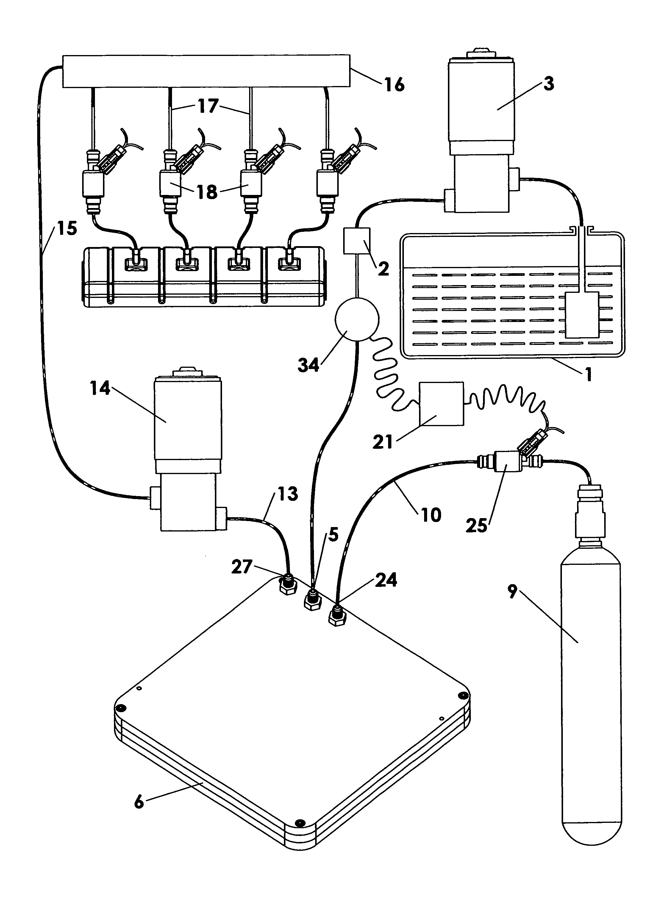
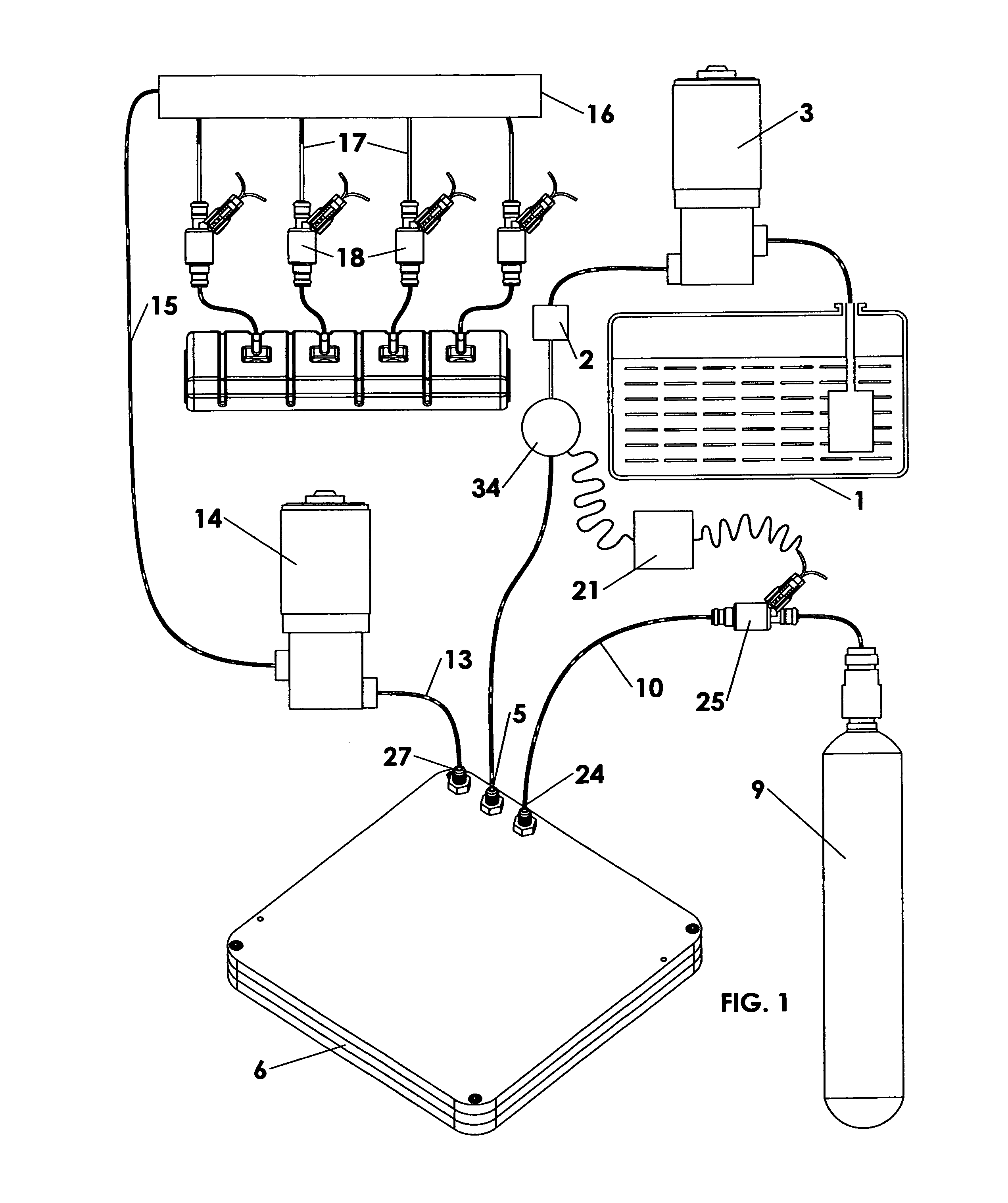
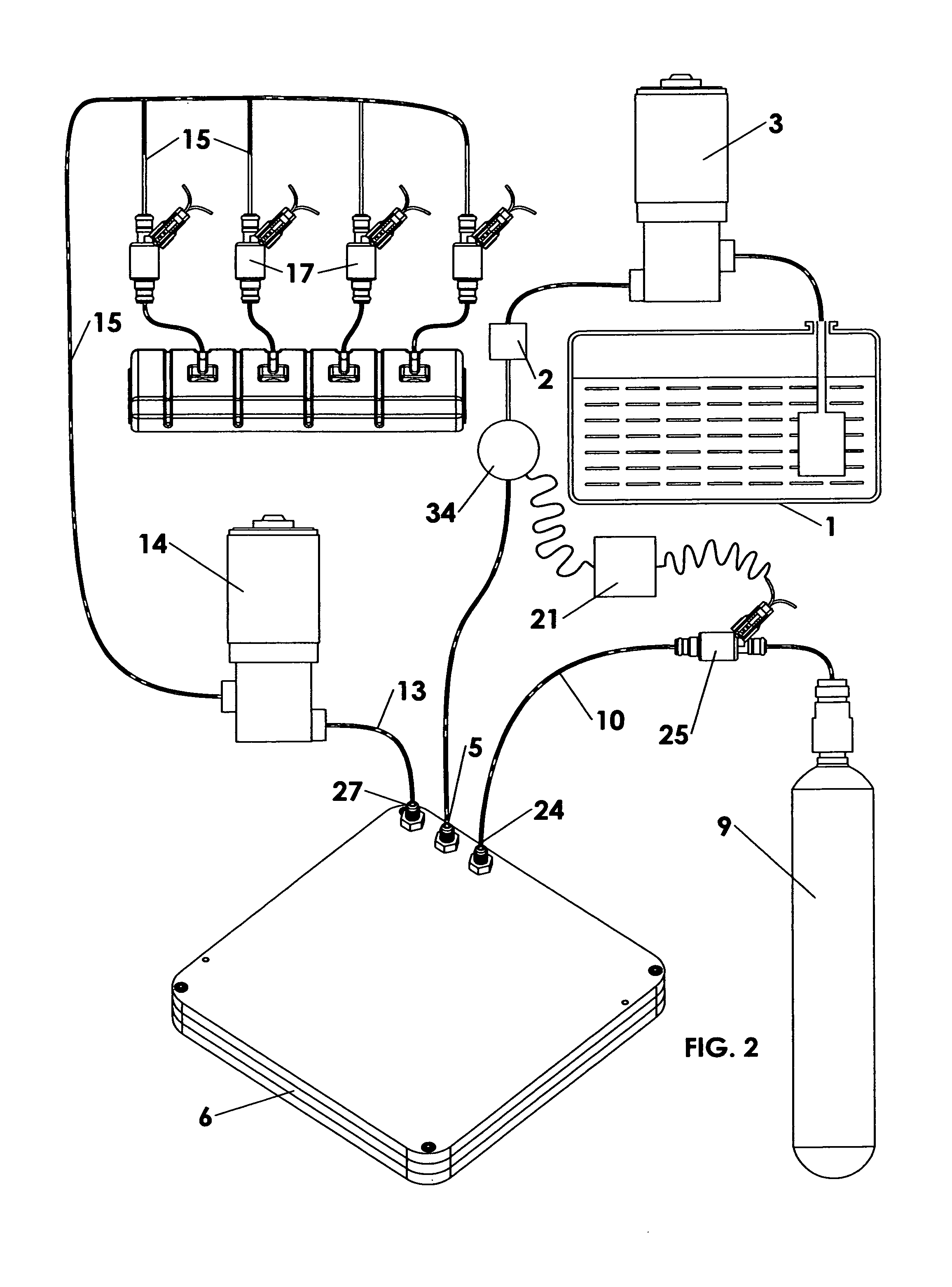
[0017]Referring now to FIG. 1 in detail, the system consists of a fuel tank 1, a fuel filter 2, and a low-pressure fuel pump 3 for delivering liquid fuel from the fuel tank 1 to the fuel inlet 5 of the fuel conditioning vessel 6. A source of liquid carbon dioxide in a siphon tube tank 9 is fluidically connected by the line 10 to the carbon dioxide inlet 24 of the vessel 6 through metering valve 25. A flow meter 34 in the fuel line measures fuel consumption. Valve 25 regulates the amount of carbon dioxide admitted to the conditioning vessel relative to the amount of fuel, the valve being controlled by the flow meter 34 through electronic control 21. A 0.375 inch tubular passage is arranged in two interconnected spirals with a total length of 28 feet in a compact rigid housing whose dimensions do not exceed 18 inches. The elongate path for the mixture results in achieving a significant amount of gas being dissolved in the fuel. An outlet port 27 located at a terminal end of the elonga...


PUM


Abstract

A fuel conditioning system is applied to common rail direct injection or unit injector diesel engines. A liquid fuel is conditioned with gas for combustion in the combustion chambers. The system includes an elongate conditioning vessel, at least one fuel dispensing inlet, at least one carbon dioxide inlet port, and at least one conditioned fuel outlet port on the vessel. Carbon dioxide and diesel fuel are fed into the inlet portion of the vessel. The mixture travels a path of at least ten feet in the vessel to the outlet portion to cause the carbon dioxide gas to dissolve in the liquid fuel for forming a liquid/gas fuel solution. At least one high-pressure fuel pump feeds the liquid fuel/gas solution into fuel injectors.

Description

[0001]This application claims the benefit of provisional patent application Ser. No. 61 / 689,195 filed Jun. 1, 1012, incorporated herein by reference in its entirety.BACKGROUND OF THE INVENTION[0002]The present invention relates to a field of liquid fuel combustion and, more particularly to delivering to a high-pressure fuel pump (or pumps) a conditioned fuel in the form of a solution in said fuel of such gases as CO2 or air or a mixture of gases with a purpose to achieve a high degree of a fuel dispersion in a combustion chamber of a reciprocating or gas turbine engine, or any other device having a combustion chamber.[0003]It is common knowledge that the dispersion of a liquid fuel within a combustion chamber results in a highly developed active surface of this liquid fuel which allows the fuel to burn fuel more efficiently. The small size of the combustion chamber in a reciprocating engine, for example, may result in the partial deposition of the injected fuel on the piston and com...

Claims


Application Information

Patent Timeline
Patent Type & Authority Patents(United States)
IPC IPC(8): F02B43/00F02M25/00F02M17/22F02B47/00
CPCF02B47/00F02M67/06F02M25/00F02M37/0064F02B43/00F02M17/22
Inventor MUCCIACCIARO, DOMENIC
Owner MUCCIACCIARO DOMENIC
Why Eureka
Try Eureka