Master unit, remote unit and multiband transmission system

a multi-band transmission system and master unit technology, applied in the direction of frequency-division multiplex, synchronisation signal speed/phase control, electromagnetic repeaters, etc., can solve the problems of inability to cleanly separate the frequency bands on the receiver side, inability to achieve the intermodulation of the frequency bands used, and inability to achieve clean separation of the frequency bands. , to achieve the effect of reducing the intensity of the reference frequency signal, reducing the characteristic of the data signal, and reducing the intensity of the reference frequency

Active Publication Date: 2014-03-25
ANDREW WIRELESS SYST GMBH
View PDF9 Cites 17 Cited by
  • Summary
  • Abstract
  • Description
  • Claims
  • Application Information

AI Technical Summary

Benefits of technology

[0023]In an embodiment of the master unit, the reference frequency generator is embodied to generate a reference frequency signal of low signal strength with a sufficient signal to noise ratio, taking into consideration harmonics and intermodulation products, from the other frequency bands of the transmission signals. It is thus ensured that the concomitantly transmitted reference frequency signal itself does not contribute to intermodulation effects. Even with a low signal strength, on the remote side the reference frequency signal can be easily restored or detected due to its simple and specific characteristics. The reference frequency signal in the simplest variant is transmitted as a sine signal.
[0024]In a further embodiment, a spread sequence generator is connected downstream of the reference frequency generator in the master unit, which spread sequence generator is used to spread the data signal of the master modem. In other words, the reference frequency generator is used for clocking the spread sequence generator. The spread sequence generator generates a spread sequence or a spread code. By means of the spread sequence of the spread code the data signal of the master modem is spread, whereby the bandwidth of the data signal is characteristically enlarged. The original signal can easily be removed again from a noise background from the spread signal, even with relatively low intensity.
[0025]In a further embodiment, the spread sequence generator is used to spread the reference frequency signal itself. The reference frequency signal is thus transmitted with the same advantages as have just been described for the data signal. In particular the intensity of the reference frequency signal can be further reduced again. The reference frequency signal can easily be regenerated from a background noise.
[0031]A frequency conversion as described above is advisable in particular when two separate signals are transmitted within frequency bands that overlap or in which at least the danger of an intermodulation exists. In order to avoid such an intermodulation in a signal transmitted by means of Frequency Division Duplexing, it is provided to convert overlapping frequency bands of the transmission signals into free intermediate frequency bands. It is assumed thereby that such free intermediate bands with sufficiently large width or distance are provided between the frequency bands of the standards for the transmission of wireless information for avoiding overlapping effects. The hitherto free intermediate bands of the overlapping frequency bands for the transmission of signals are used by the described approach. In other words, overlapping frequency bands of different signals are distributed among the free intermediate bands so that overall a clear reduction of intermodulation effects, etc. occurs. Preferably, with a number n of overlapping frequency bands only a number of n−1 can thereby be converted into free intermediate frequency bands, while one of these signals is carried out on its frequency without conversion. The intermodulation problem is hereby avoided with low expenditure to the same extent.

Problems solved by technology

In the transmission of signals between the master unit and the remote unit by means of frequency division duplexing, and in particular also with the simultaneous transmission of digital and analog signals, an undesirable intermodulation between the frequency bands used can occur.
A clean separation of the frequency bands on the receiver side may be no longer possible.

Method used


Image

  • Master unit, remote unit and multiband transmission system
  • Master unit, remote unit and multiband transmission system
  • Master unit, remote unit and multiband transmission system

Examples


Embodiment Construction

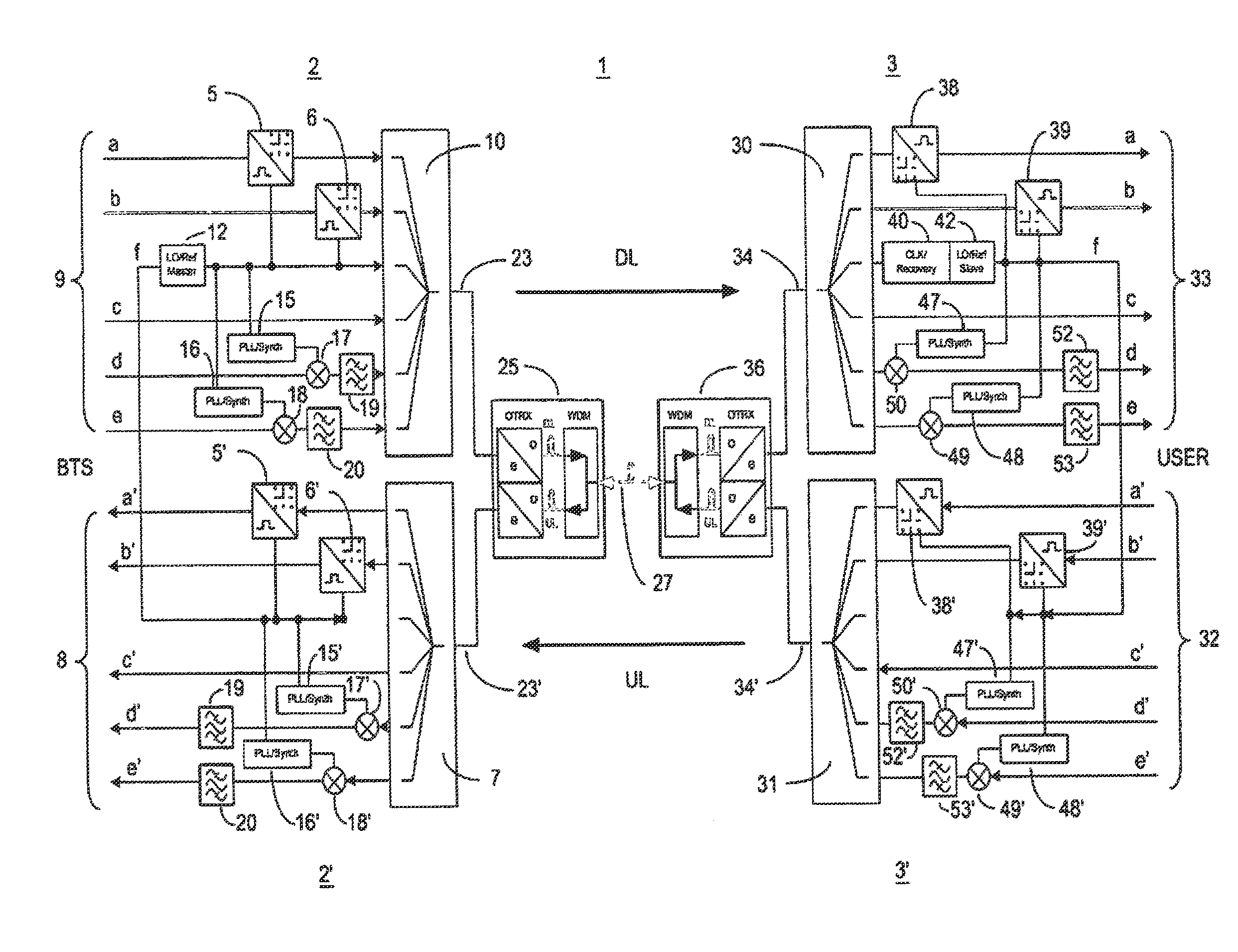
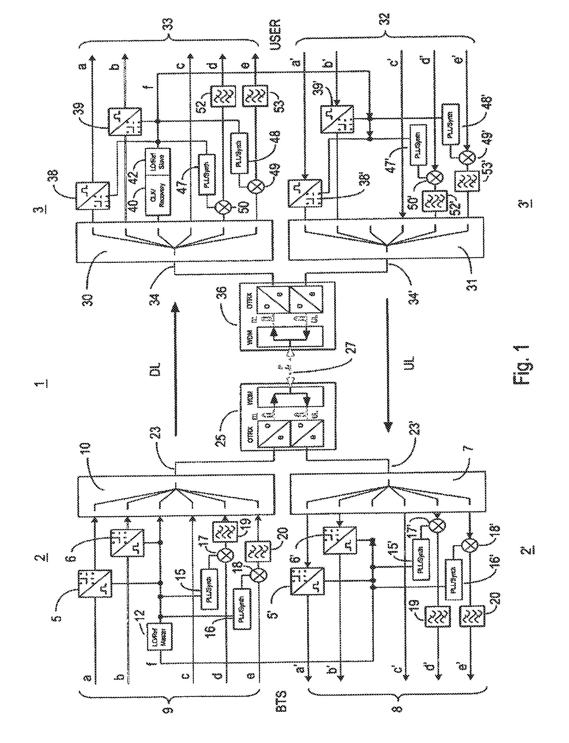
[0043]FIG. 1 shows diagrammatically the common transmission of signals of two digital networks and of signals of three wireless communication networks between a master unit 2, 2′ and a remote unit 3, 3′. The master unit 2, 2′ and the remote unit 3, 3′ together form a multiband transmission system 1 for distributing and combining signals of at least one wireless communication network and of at least one digital network. The downlink region is hereby labeled by 2, 3, while the uplink region is given by 2′ and 3′.

[0044]The master unit 2, 2′ hereby comprises signal lines a, b or a′, b′ for transmitting or exchanging signals within respectively one digital network. The digital data before transmission by means of a first master modem 5 and by means of a second master modem 6 are hereby modulated on a carrier frequency. Both master modems 5, 6 are hereby embodied for a multi QAM modulation. In the uplink direction the further master modems 5′ and 6′ are provided for the demodulation of th...


PUM


Abstract

A master unit and a remote unit is provided for a multiband transmission system for distributing and combining signals of at least one wireless communication network and at least one digital network. A reference frequency generator is arranged in the master unit, the reference frequency generator being designed to clock a master modem for converting the signals of the at least one digital network. The reference frequency signal emitted by the reference frequency signal is restored via a reference frequency receiver and is used for closing a remote modem that is located there for demodulation.

Description

[0001]This is a continuation of International Application No. PCT / EP2010 / 006797, which was filed on Nov. 9, 2010, and which claims priority to German Patent Application No. DE 10 2009 052 936.5, which was filed in Germany on Nov. 12, 2009, and which are both herein incorporated by reference.BACKGROUND OF THE INVENTION[0002]1. Field of the Invention[0003]The invention relates to a master unit and to a remote unit for distributing and combining signals of at least one wireless communication network and of at least one digital network. The invention further relates to a multiband transmission system with a master unit of this type and with a remote unit of this type.[0004]2. Description of the Background Art[0005]A multiband transmission system of the above-mentioned type is basically used for distributing and combining signals of at least one wireless communication network and of at least one digital network. The master unit is hereby used for relaying and amplifying signals between a...

Claims


Application Information

Patent Timeline
Patent Type & Authority Patents(United States)
IPC IPC(8): H04L7/06H04L27/26H04B1/38H04J14/00H04B10/29
CPCH04W88/085H04L7/06H04B7/15542
Inventor BRAZ, OLIVEREISENWINTER, STEFANSCHMALISCH, MATHIASSTEFANIK, JOERGSCHMID, PETER
Owner ANDREW WIRELESS SYST GMBH
Why Eureka
Try Eureka