System and method for path rendering with multiple stencil samples per color sample

a path and stencil technology, applied in the field of graphic processing, can solve the problems of creating a substantial cpu burden, challenging the path arc computation, and unable to solve the problem of a tractable closed form solution for computing the length of a cubic bèzier segment or partial elliptical arc, so as to achieve high-quality anti-aliasing path object rendering, the effect of improving the overall path rendering performan

Active Publication Date: 2014-04-22
NVIDIA CORP
View PDF42 Cites 3 Cited by
  • Summary
  • Abstract
  • Description
  • Claims
  • Application Information

AI Technical Summary

Benefits of technology

The disclosed technique described in this patent improves the performance of computer systems by better utilizing resources in the GPU to achieve higher path rendering performance. This allows for high-quality, anti-aliased path object rendering within the GPU.

Problems solved by technology

Dashing curved paths is challenging because it requires the computation of incremental arc lengths along a dashed path.
Computing the length of a cubic Bèzier segment or partial elliptical arc lacks a tractable closed form solution and is therefore extremely difficult.
This process can create a substantial CPU burden.
Tessellation is a fragile, often quite sequential, process that requires global inspection of the entire path.
Path rendering makes this process considerably more difficult by permitting curved path segments as well as allowing path segments to self-intersect, form high genus topologies, and be unbounded in size.
Performance burdens associated with complex CPU-based tessellation for GPU-based rendering can result in poor overall performance.
A general problem with using a GPU to render paths is unacceptably poor antialiasing quality when compared to standard CPU-based methods.
The problem is that GPUs employ point sampling for rasterization of triangular primitives with only 1 to 8 samples (often 4) per pixel.
Adding more samples per pixel based on conventional surface allocation techniques is not a scalable approach for GPU-based path rendering.
Additional color samples can have high secondary cost associated with memory bandwidth, processing burden, and power consumption for clearing, shading, blending, and down-sampling the additional color samples for display.
Furthermore, path shading typically does not utilize a depth test, meaning each three-byte depth value goes unused.
Animating or editing paths is costly because it requires re-tessellating the entire path since the tessellation is resolution and view dependent, and in general it is very difficult to prove a local edit to a path will not cause a global change in the tessellation of the path.
In particular, this means the sub-paths of a path cannot be processed separately without first determining that no two sub-paths overlap.
These requirements, combined with the generally fragile and sequential nature of tessellation algorithms make path tessellation particularly expensive.
Unfortunately such tessellations are much less compact than the original path representations, particularly when curved path segments are involved.
Cached tessellations are also ineffective when paths are animated or rendered just once.
These offset curves are typically of much higher degree of complexity compared with the linear segments that are traced to generate the stroked path.
Determining whether or not each pixel is inside or outside of a stroked path to generate a given stroke is mathematically complex.
While more mathematically complex path segments representations could be used to specify paths, in practice, existing standards limit themselves to the aforementioned path segment types.
Filling and stroking operations on the curves and arcs are also more complex than conventional line and convex polygon rasterization because paths are unbounded in their complexity whereas line segments and triangles are defined by just 2 or 3 points respectively.
In other words, it is quite unreasonable to try to determine exactly the boundary representation of such offset curves and then simply fill them.
However, for the reasons described above, path rendering in the prior art does not benefit as significantly from GPU involvement.

Method used


Image

  • System and method for path rendering with multiple stencil samples per color sample
  • System and method for path rendering with multiple stencil samples per color sample
  • System and method for path rendering with multiple stencil samples per color sample

Examples


Embodiment Construction

[0048]In the following description, numerous specific details are set forth to provide a more thorough understanding of the present invention. However, it will be apparent to one of skill in the art that the present invention may be practiced without one or more of these specific details. In other instances, well-known features have not been described in order to avoid obscuring the present invention.

System Overview

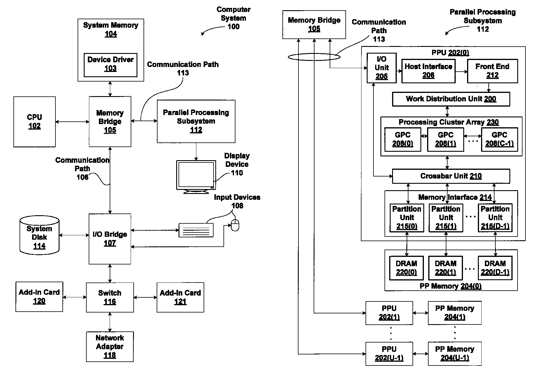
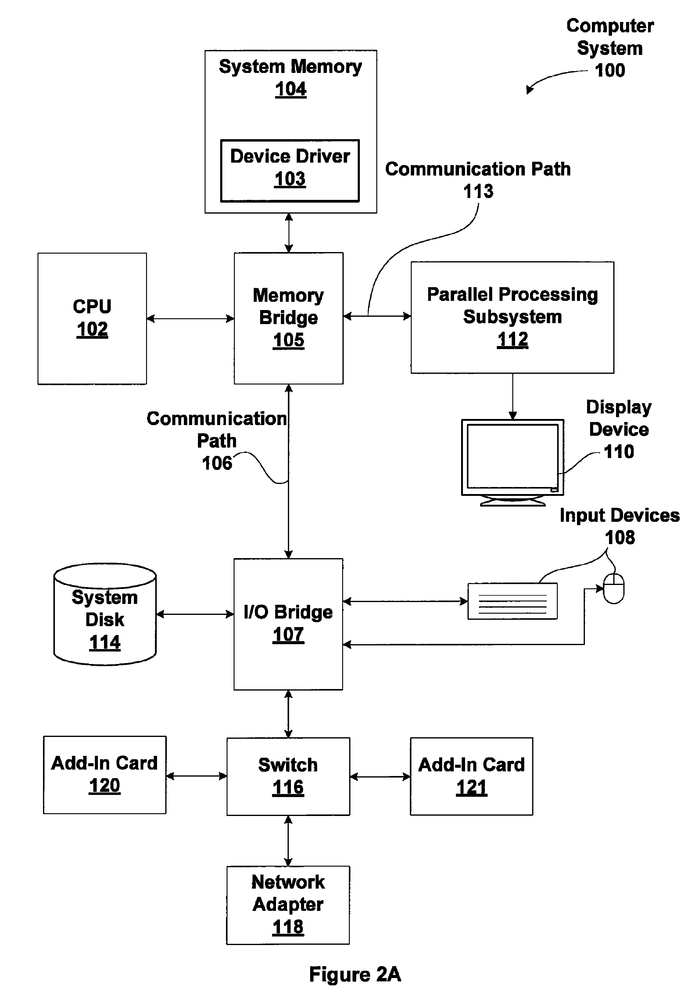
[0049]FIG. 2A is a block diagram illustrating a computer system 100 configured to implement one or more aspects of the present invention. Computer system 100 includes a central processing unit (CPU) 102 and a system memory 104 communicating via an interconnection path that may include a memory bridge 105. Memory bridge 105, which may be, e.g., a Northbridge chip, is connected via a bus or other communication path 106 (e.g., a HyperTransport link) to an I / O (input / output) bridge 107. I / O bridge 107, which may be, e.g., a Southbridge chip, receives user input from one or mo...


PUM


Abstract

One embodiment of the present invention sets forth a technique for improving path rendering on computer systems by efficiently representing and computing sub-pixel coverage for path objects. A stencil buffer is configured to store multiple stencil samples per pixel stored in an image buffer. The stencil samples undergo stencil testing to produce a set of Boolean values per pixel, which collectively define a geometric coverage percentage for the pixel. The coverage percentage is used to modulate a color value for the pixel. The modulated color value is then blended into the image buffer as an anti-aliased pixel. This technique advantageously enables efficient anti-aliasing for path rendering.

Description

CROSS-REFERENCE TO RELATED APPLICATIONS[0001]This application claims priority benefit to U.S. provisional patent application titled, “Path Rendering,” filed on May 21, 2010 and having Ser. No. 61 / 347,359. This related application is also hereby incorporated by reference in its entirety.BACKGROUND OF THE INVENTION[0002]1. Field of the Invention[0003]The present invention generally relates to graphics processing and more specifically to a system and method for path rendering with multiple stencil samples per color sample.[0004]2. Description of the Related Art[0005]Path rendering is a style of resolution-independent two-dimensional (2D) rendering that is the basis for a number of important rendering standards such as PostScript, Java 2D, Apple's Quartz 2D, OpenVG, PDF, TrueType fonts, OpenType fonts, PostScript fonts, Scalable Vector Graphics (SVG) web format, Microsoft's Silverlight and Adobe Flash for interactive web experiences, Open XML Paper Specification (OpenXPS), drawings in O...

Claims


Application Information

Patent Timeline
Patent Type & Authority Patents(United States)
IPC IPC(8): G06T15/40
CPCG06T15/005G06T11/203
Inventor KILGARD, MARK J.BROWN, PATRICK R.
Owner NVIDIA CORP
Why Eureka
Try Eureka