Process for producing regenerated hydrotreating catalyst and process for producing petrochemical product

a technology of regenerated hydrotreating catalyst and catalyst, which is applied in the direction of physical/chemical process catalyst, other chemical processes, separation processes, etc., can solve the problems of increasing catalyst cost and waste catalyst amount, and achieves the effect of reducing cost, reducing waste catalyst, and reducing catalyst cos

Inactive Publication Date: 2014-05-13
JX NIPPON OIL & ENERGY CORP
View PDF12 Cites 30 Cited by
  • Summary
  • Abstract
  • Description
  • Claims
  • Application Information

AI Technical Summary

Benefits of technology

[0024]The process for producing a regenerated hydrotreating catalyst of the present invention has an advantage of being capable of easily producing a regenerated hydrotreating catalyst having a sufficient activity. In addition, the process for producing a petroleum product of the present invention can achieve a highly practical producing process using a regenerated hydrotreating catalyst having a sufficient activity with a lower price and is remarkably useful in terms of reduction of cost, reduction of an emission amount of waste product, efficiency in hydrotreatment of a distillate petroleum fraction, production of a petroleum product with higher quality, and so on.

Problems solved by technology

As a result, frequency of the replacement of the catalyst is increased, which leads to an increase in catalyst cost and an increase in an amount of waste catalyst.

Method used


Image

  • Process for producing regenerated hydrotreating catalyst and process for producing petrochemical product
  • Process for producing regenerated hydrotreating catalyst and process for producing petrochemical product
  • Process for producing regenerated hydrotreating catalyst and process for producing petrochemical product

Examples


example 1

Regenerated Hydrotreating Catalyst

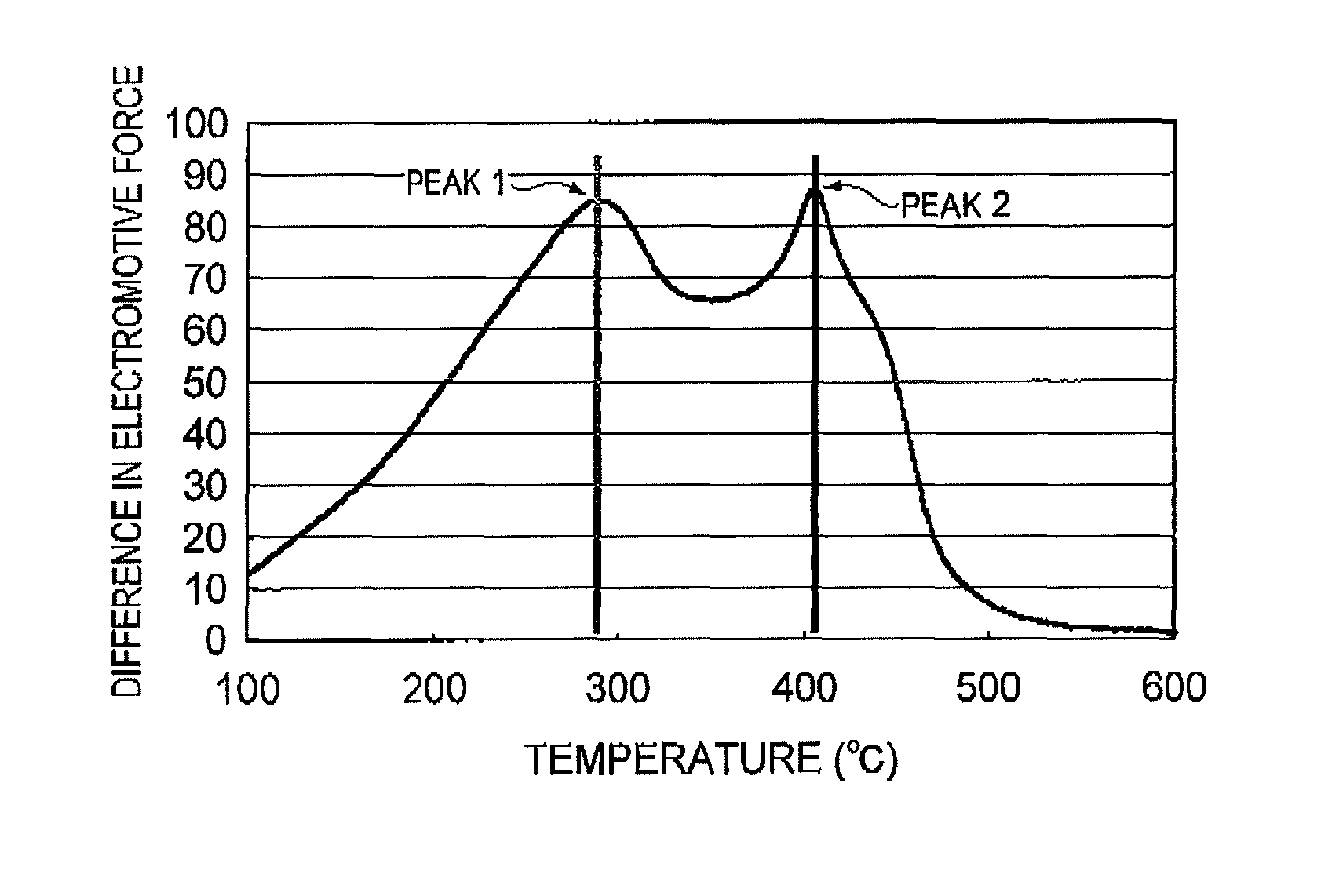
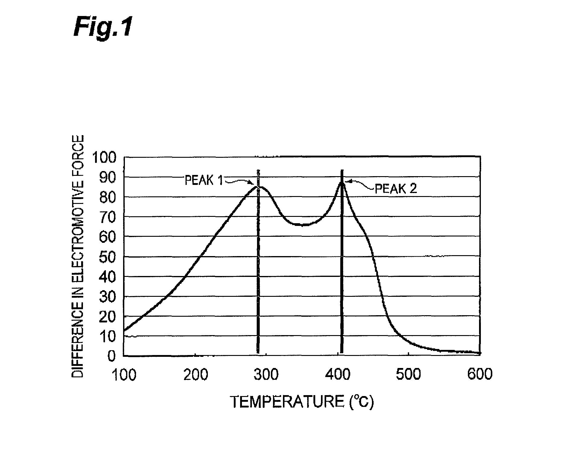
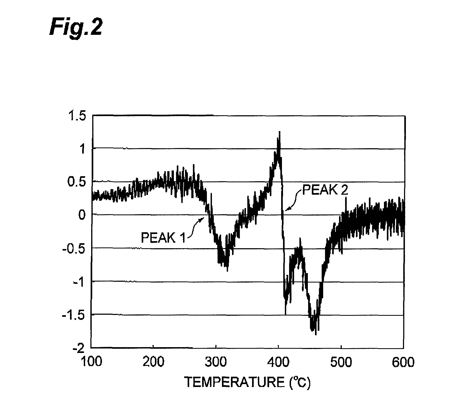
[0060]A spent hydrotreating catalyst 1 which was a catalyst containing molybdenum and cobalt as active metals supported on an alumina support and was pulled out after having been used in a hydrotreating facility for kerosene for two years was prepared. 5.139 mg of the spent hydrotreating catalyst 1 was measured out into a platinum pan, set in a differential thermal analyzer (Thermo Plus 2 series / TG8110 manufactured by Rigaku Corporation), and subjected to a differential thermal analysis with elevating a temperature of a sample from room temperature to 700° C. by 10° C. / minute at a flow rate of air of 100 ml / minute. Next, T1 and T2 were calculated by the aforementioned method based on the results of the differential thermal analysis, which revealed that T1=260° C. and T2=360° C. Deoiling was carried out by heating the spent hydrotreating catalyst 1 at 300° C. for 3 hours in a nitrogen flow having a flow rate per unit volume of the spent catalyst of 1...

example 2

Regenerated Hydrotreating Catalyst

[0063]A regenerated catalyst 2 was obtained by using the same spent hydrotreating catalyst 1 as that used in Example 1 and by carrying out regeneration by the same operation as that in Example 1 except that regeneration conditions were those shown in Table 1. The analysis results of a residual carbon content in the regenerated catalyst 2 are shown in Table 1.

[0064](Hydrotreatment Reaction)

[0065]A hydrotreatment reaction was carried out by the same operation as that in Example 1 except that the regenerated catalyst 2 was used. The results of specific activity are shown in Table 1.

example 3

Regenerated Hydrotreating Catalyst

[0066]A spent hydrotreating catalyst 2 which was a catalyst containing molybdenum and cobalt as active metals supported on an alumina support and was pulled out after having been used in a hydrotreating facility for a gas oil for two years was prepared. The spent hydrotreating catalyst 2 was subjected to a differential thermal analysis, which revealed that T1=310° C. and T2=410° C. Deoiling was carried out by heating the spent hydrotreating catalyst 2 at 400° C. for 3 hours in a nitrogen flow having a flow rate per unit volume of the spent catalyst of 15 NL / h·L-catalyst in an electric furnace. After that, a regenerated catalyst 3 was obtained by regenerating the deoiled catalyst at T2−10° C. for 5 hours in an air flow having a flow rate per unit volume of the catalyst of 50 NL / h·L-catalyst in the electric furnace. Quantitative determination of a residual carbon content in the obtained regenerated catalyst 1 was carried out by the aforementioned test...


PUM

PropertyMeasurementUnit
temperatureaaaaaaaaaa
flow rateaaaaaaaaaa

Abstract

Provided is a process for producing a regenerated hydrotreating catalyst by regenerating a spent hydrotreating catalyst in a prescribed temperature range, wherein the prescribed temperature range is a temperature range of T1−30° C. or more and T2+30° C. or less, as determined by subjecting the spent hydrotreating catalyst to a differential thermal analysis, converting a differential heat in a measuring temperature range of 100° C. or more and 600° C. or less to a difference in electromotive force, differentiating the converted value twice by temperature to provide a smallest extreme value and a second smallest extreme value, and representing a temperature corresponding to the extreme value on the lower-temperature side as T1 and a temperature corresponding to the extreme value on the higher-temperature side as T2.

Description

TECHNICAL FIELD[0001]The present invention relates to a process for producing a regenerated hydrotreating catalyst for treating a distillate petroleum fraction and a process for producing a petroleum product made from a distillate petroleum fraction.BACKGROUND ART[0002]Sulfur-containing compounds, nitrogen-containing compounds, oxygen-containing compounds, and the like are contained in crude petroleum as impurities and these impurities are also contained in distillate petroleum fractions obtained by distilling the crude petroleum. The impurities in these distillate petroleum fractions are reduced in their contents by a step of bringing the fractions into contact with a catalyst having a hydrogenation activity in the presence of hydrogen, the step being referred to as hydrotreatment. Especially, desulfurization for reducing contents of the sulfur-containing compounds is well known. Recently, from the viewpoint of reducing environmental load, there has been stricter demand for control...

Claims


Application Information

Patent Timeline
Patent Type & Authority Patents(United States)
IPC IPC(8): C10G65/02
CPCC10G45/72B01J38/02C10G2300/4081C10G49/26C10G47/36C10G49/02C10G2300/701
Inventor KONNO, SOUICHIROUIWANAMI, YOSHIMUSAHARA, WATARUKIMURA, NOBUHARU
Owner JX NIPPON OIL & ENERGY CORP
Why Eureka
Try Eureka