Wideband high gain antenna

a high-gain, wideband technology, applied in the direction of slot antennas, antenna details, antennas, etc., can solve the problems of insufficient timing of the plurality of incoming signals, insufficient electrical connection of the plurality of radiator elements within the tower, and insufficient electrical impedance accounting. , to achieve the effect of excellent transmission and reception capability

Inactive Publication Date: 2014-05-20
MESH CITY WIRELESS
View PDF3 Cites 5 Cited by
  • Summary
  • Abstract
  • Description
  • Claims
  • Application Information

AI Technical Summary

Benefits of technology

[0033]In the range between 470-860 MHZ, the radiator element disclosed provides excellent performance with a measured loss below −9.8 db which means that the Voltage Standing Wave Radio is 2:1 over this entire frequency band. In the 680 MHz to 2100 MHZ band, the radiator element can concurrently provide excellent performance with a measured return loss of less than −9.8 dB. Similar concurrent performance characteristics are achieved in the bandwidth between 2.0 GHz to 6.0 Ghz.
[0067]It is an additional object of this invention, to provide an antenna element engageable to a portable device such as a smartphone, which provides excellent transmission and reception capability across multiple bands employing multiple communications standards.

Problems solved by technology

This can result in multiple antenna towers, within yards of each other, on a hill, tall towers or other high points servicing surrounding areas.
Such duplication of effort is not only expensive, it tends to be an eyesore in the community.
Further the conventional methods of electrically connecting the plurality of radiator elements within these towers similarly fall short.
However, such typical methods fall short in accounting for electrical impedance, as well as the timing of the plurality of incoming signals.
Such timing problems rise from unequal transmission line length or from placement of antenna elements in positions where signals arrive at different times. While modern receivers can be adapted to tune out and ignore such signals, this can decrease the signal strength to the device in need of it.
As a result, along with the eyesore of having multiple antenna towers within yards of each other, transmitted and received signals, from separate antenna elements, may not be of the best quality.
As such, when constructing a communications array such as a cellular antenna grid, or a wireless communications web, the builder is faced with the dilemma of obtaining antennas that are customized by providers for the narrow frequency to be serviced.
However, such antennas once manufactured to specific individual frequencies or narrow frequency bands, offer little means of adjustment of their ultimate frequency range, and their gain since they are general fixed in nature.
Further, since they are custom manufactured to the frequency band, gain, polarization, beam width, and other requirements, should technology change or new frequencies become available, it can be a problem since new antennas are required to mach the changes.
Without stocking a large inventory of antennas, delays in installation can occur.
Such an inventory requirement increases costs tremendously as well as deployment lead time if the needed antenna configuration is not at hand.
Further, during installation, it is hard to predict the final antenna construction configuration since in a given topography what works on paper may not work in the field.
Additionally, what exact gain and polarization or frequency range which might be required for a given system, when it is being installed might not match predications.
The result being that a delay will inherently occur where custom antennas must be manufactured for the user if they are not stocked.
This not only severely limits the location of individual antenna nodes in such a grid, it substantially increases the costs since each antenna services a finite number of users and it must be hardwired to a local network on the ground.
A similar problem arises with the user of the various transmitted RF signals from these differing antenna sites, as well as from local transmission and reception sites for communications over Wi-Fi and bluetooth.

Method used


Image

  • Wideband high gain antenna
  • Wideband high gain antenna
  • Wideband high gain antenna

Examples


Embodiment Construction

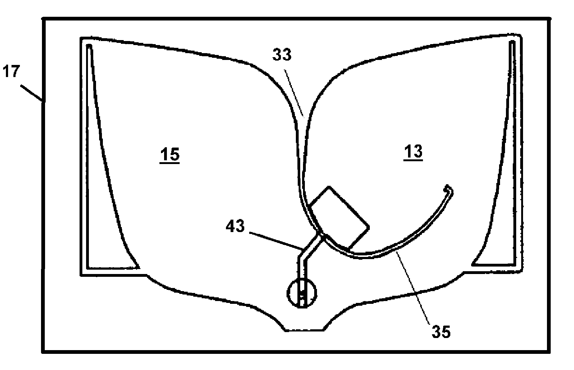
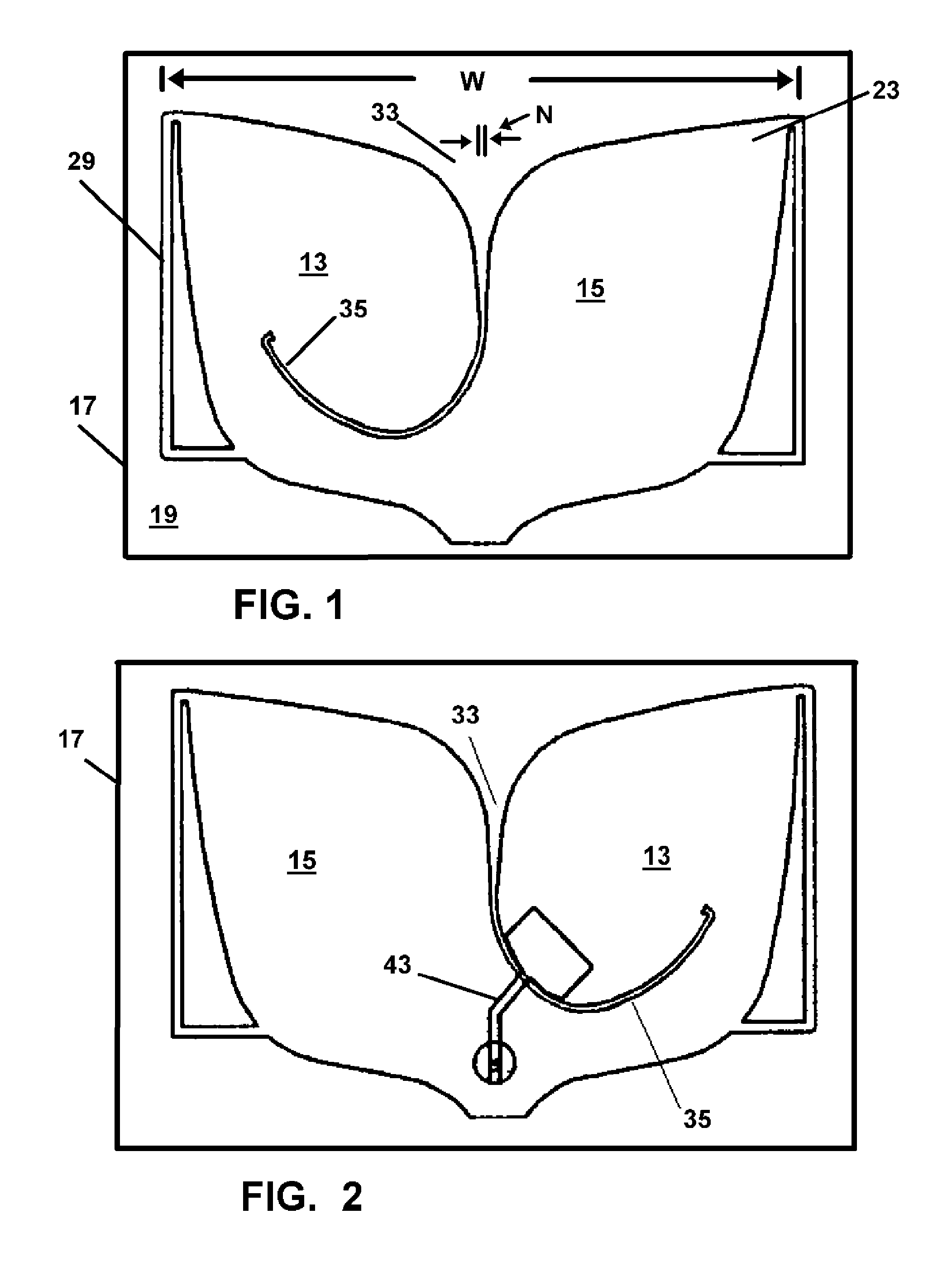
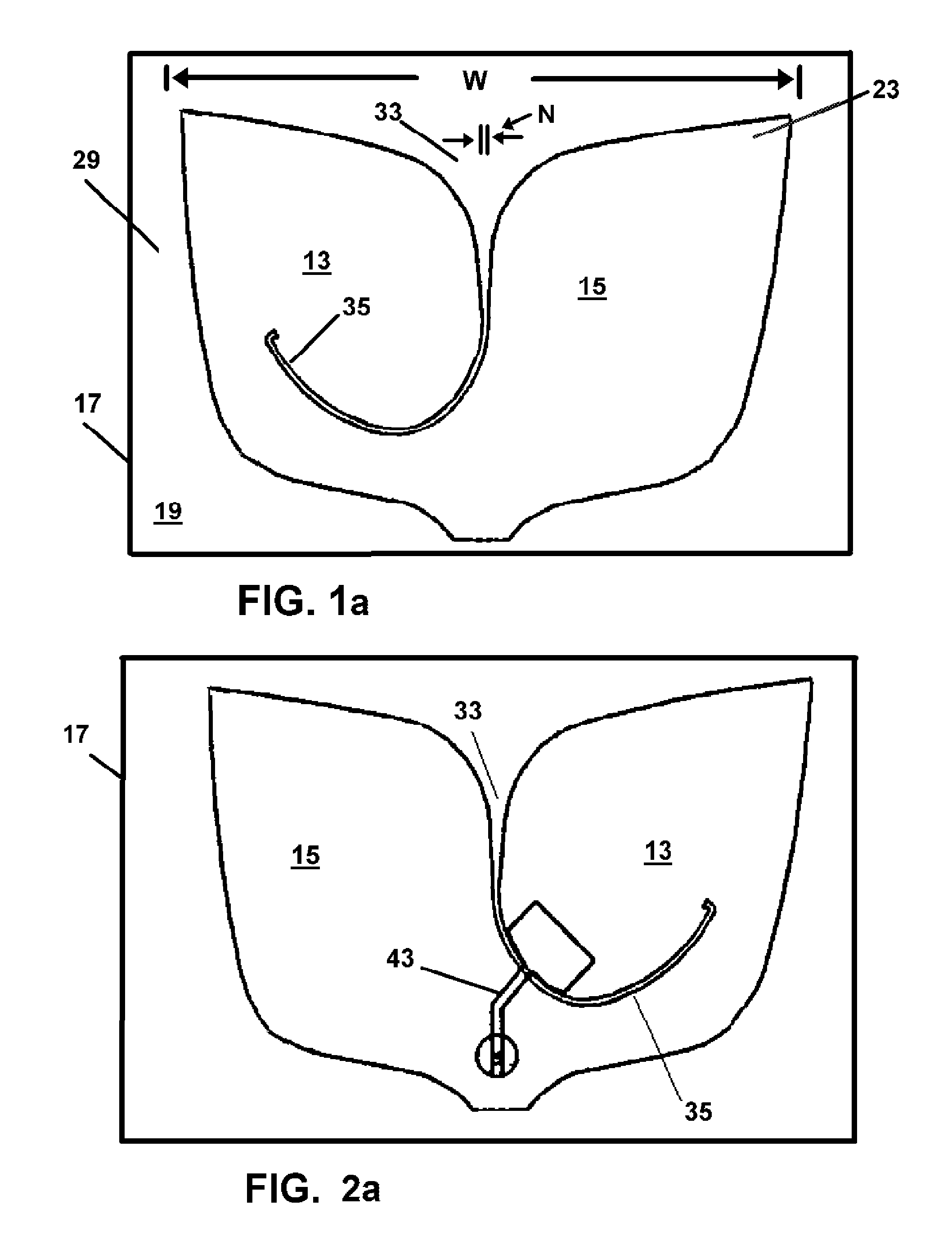
[0087]Referring now to the drawings of FIGS. 1-13, in FIGS. 1 and 2, depicting the radiator element 22 of the device 10, the radiator element 22 shaped much like a “whale tail” is depicted having two halves which are formed by a first horn 13 and second horn 15 looking much like leaves and being substantially identical or mirror images of each other. Each radiator element 22 of the invention is formed on a substrate 17 which as noted is non conductive and may be constructed of either a rigid or flexible material such as, MYLAR, fiberglass, REXLITE, polystyrene, polyamide, TEFLON fiberglass, or any other such material which would be suitable for the purpose intended.

[0088]A first surface 19 is coated with a conductive material by microstripline or the like or other metal and substrate construction well known in this art. Any means for affixing the conductive material to the substrate is acceptable to practice this invention. The conductive material 23 as for example, include but are ...


PUM


Abstract

An antenna array formed of individual electrically connected pluralities of wideband antenna elements. The array features a centrally located rectangular ground plane having a top surface defined by four edges. Each of said pluralities of elements is engaged to a separate substrate which is engaged along one of the four edges. The substrates may be angled to adjust the footprint of the antenna.

Description

[0001]This application is a Continuing in Part application of U.S. patent application Ser. No. 12 / 419,213 filed on Apr. 6, 2009 now U.S. Pat. No. 8,063,841 which claims the benefit of U.S. Provisional Application Ser. No. 61 / 075,296, filed on Jun. 24, 2008, all of which are respectively incorporated herein in their entirety by this reference thereto.BACKGROUND OF THE INVENTION[0002]1. Field of the Invention[0003]The present invention relates to antennas for transmission and reception of radio frequency communications in a plurality of RF bands concurrently using the same element. More particularly, the present invention relates generally to an antenna array formed of a plurality of wideband-capable antenna elements, or radiators, which is capable of operating at any frequency between 800 MHZ and 3000 MHZ at substantially 6 dBi. The resulting array has a circular radiation and reception pattern which may also be adjusted to radiate up or down depending on orientation of side engaged ...

Claims


Application Information

Patent Timeline
Patent Type & Authority Patents(United States)
IPC IPC(8): H01Q13/10
CPCH01Q21/0087H01Q21/064H01Q1/246H01Q21/00H01Q13/085H01Q1/523H01Q13/106H01Q21/293
Inventor PENG, SHENGSAMUELS, GEORGECOOPER, HENRY
Owner MESH CITY WIRELESS
Why Eureka
Try Eureka