Capacitive chemical sensor

a capacitive chemical sensor and capacitive technology, applied in the field of chemical sensing, can solve the problems of insufficient analyte collection for detection or proper identification, insufficient sample material collection, and waste of precious time collected, so as to prolong the service life of the sensor, enhance the preferential adsorption or reaction, and similar or greater film impedance shift

Active Publication Date: 2014-05-27
NAT TECH & ENG SOLUTIONS OF SANDIA LLC
View PDF7 Cites 22 Cited by
  • Summary
  • Abstract
  • Description
  • Claims
  • Application Information

AI Technical Summary

Benefits of technology

[0010]The chemical sensors can provide autonomous, selective, and sensitive chemical sensing for remote or unattended operation. Dielectric films can be chosen that chemically react with target analytes to produce changes in the capacitance of the sensor. Reactions can vary from simple compound formation, to etching, to selective cleaving of functional groups. Such reactions would produce similar or greater film impedance shifts when compared to simple adsorption. Further, sensor heating allows control of thermally-sensitive reaction and adsorption mechanisms. By maintaining a preselected set point temperature, preferential adsorption or reaction can be enhanced to provide for additional analyte selectivity and signal control. Additionally, heating enables the sensor to be cleaned by thermally-desorbing unwanted species. This periodic cleaning may extend the sensor's operational lifetime. The analyte/chemical film reaction/adsorption mechanism can occur independent of the system's power status or, in the case of a reaction requiring membrane heating, with extremely low-power output. For more remo

Problems solved by technology

When concentrations of potential toxins are high, precious time is wasted collecting excess sample material.
Furthermore, this excess material will often saturate the preconcentrator and overwhelm a detector, ne

Method used


Image

  • Capacitive chemical sensor
  • Capacitive chemical sensor
  • Capacitive chemical sensor

Examples


Embodiment Construction

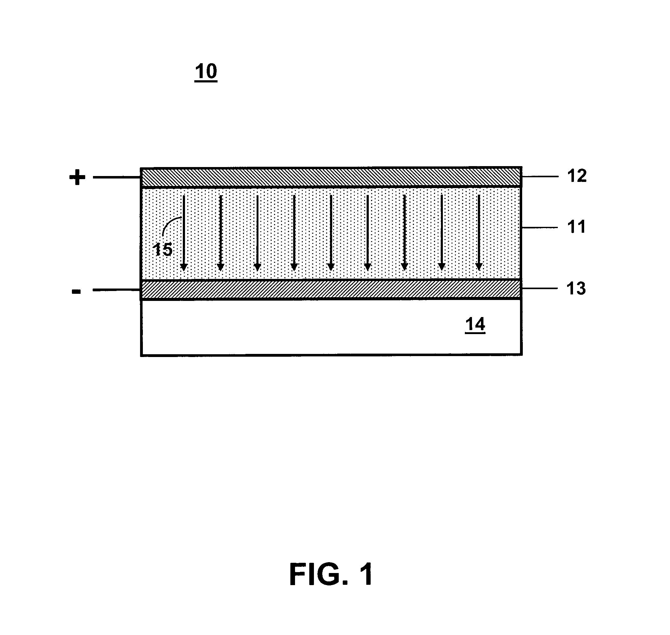
[0022]In FIG. 1 is shown a conceptual illustration of a parallel-plate capacitive sensor 10 comprising a dielectric material 11 sandwiched between opposing parallel-plate electrodes 12 and 13 disposed on an electrically insulating substrate 14. A voltage source (not shown) is connected to the driving electrode 12 and the sensing electrode 13 is connected to the input of an impedance measuring circuit (not shown). Field lines 15 go from the positive electrode 12 to the negative electrode 13. Oscillating signals from an alternating-current voltage source can be input to the driving electrode 12 to establish an alternating electric field between the driving and sensing electrodes 12 and 13. The sensing electrode 13 detects the mutual capacitance between the two electrodes 12 and 13. The mutual capacitance C of a parallel-plate capacitor is given by:

C=κ∈oA / d

where A is the area of the plates, d is the distance between the plates, ∈o is the permittivity constant, and κ is the dielectric ...


PUM


Abstract

A microfabricated capacitive chemical sensor can be used as an autonomous chemical sensor or as an analyte-sensitive chemical preconcentrator in a larger microanalytical system. The capacitive chemical sensor detects changes in sensing film dielectric properties, such as the dielectric constant, conductivity, or dimensionality. These changes result from the interaction of a target analyte with the sensing film. This capability provides a low-power, self-heating chemical sensor suitable for remote and unattended sensing applications. The capacitive chemical sensor also enables a smart, analyte-sensitive chemical preconcentrator. After sorption of the sample by the sensing film, the film can be rapidly heated to release the sample for further analysis. Therefore, the capacitive chemical sensor can optimize the sample collection time prior to release to enable the rapid and accurate analysis of analytes by a microanalytical system.

Description

STATEMENT OF GOVERNMENT INTEREST[0001]This invention was made with Government support under contract no. DE-AC04-94AL85000 awarded by the U.S. Department of Energy to Sandia Corporation. The Government has certain rights in the invention.FIELD OF THE INVENTION[0002]The present invention relates to chemical sensing and, in particular, to a microfabricated capacitive chemical sensor that can use parallel-plate or fringing-field electrodes to measure the concentration of a chemical species in a gaseous or liquid environment by detecting the change in the dielectric properties of a chemically-sensitive dielectric material film.BACKGROUND OF THE INVENTION[0003]Chemical sensors are routinely used for the detection of various gases, chemicals, moisture, organic impurities, etc. in an ambient environment. Chemical sensors combine a chemically-sensitive interface, which sorbs chemical species (i.e., analytes) from the environment, with a physical transducer that provides an electrical output...

Claims


Application Information

Patent Timeline
IPC IPC(8): H01L29/78
CPCH01L29/78G01N27/221G01N30/12G01N27/22
Inventor MANGINELL, RONALD P.MOORMAN, MATTHEW W.WHEELER, DAVID R.
Owner NAT TECH & ENG SOLUTIONS OF SANDIA LLC
Why Eureka
Try Eureka