Methods for crimping a polymeric scaffold to a delivery balloon and achieving stable mechanical properties in the scaffold after crimping

a polymer scaffold and delivery balloon technology, applied in the field of drugeluting medical devices, can solve the problems of loss of radial strength and/or fracture, long time-consuming and laborious, stress build-up in the crimped scaffold, etc., and achieve the effect of reducing the stress relaxation period following crimping, increasing the retention force of the crimped polymer scaffold, and reducing the diameter of the scaffold

Inactive Publication Date: 2014-06-17
ABBOTT CARDIOVASCULAR
View PDF13 Cites 20 Cited by
  • Summary
  • Abstract
  • Description
  • Claims
  • Application Information

AI Technical Summary

Benefits of technology

[0013]It has been found that the retention force of a crimped polymer scaffold on a delivery balloon may be increased by a process that includes crimping the scaffold to the balloon while the balloon is pressurized; that is, the balloon is pressurized at the same time as the scaffold's diameter is being reduced by crimper blades. Additionally, it has been found that if a crimping temperature is raised to about the onset of the glass transition temperature (TG) for the polymer, or slightly higher than this temperature, the stress relaxation period following crimping can be reduced significantly over previous methods that had crimped at temperatures below TG.
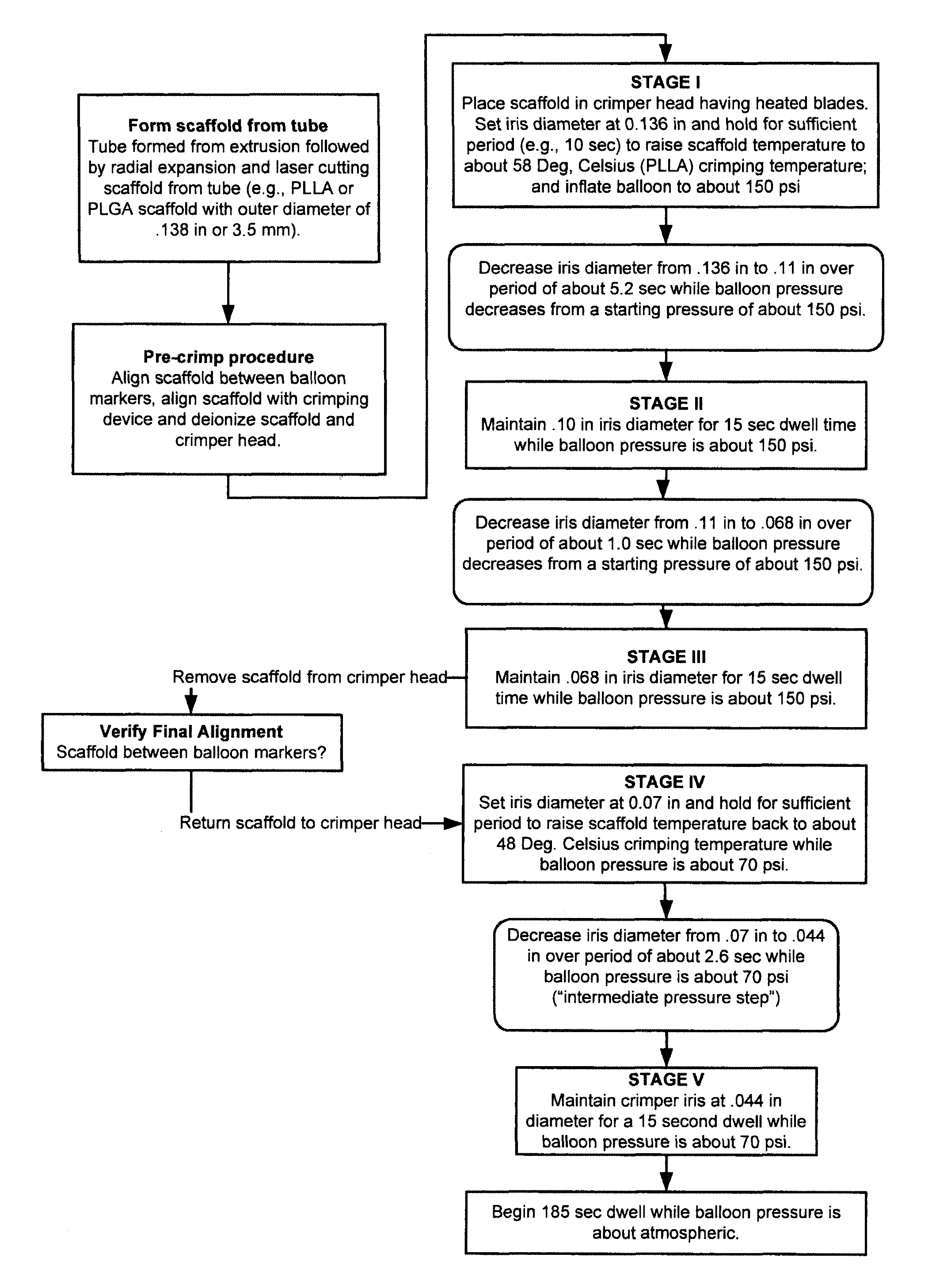
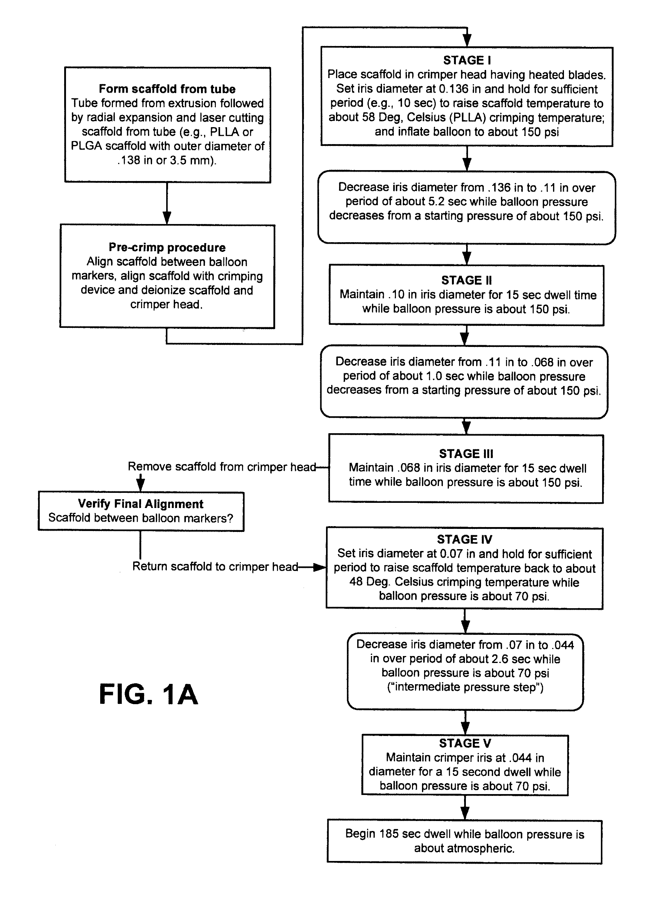
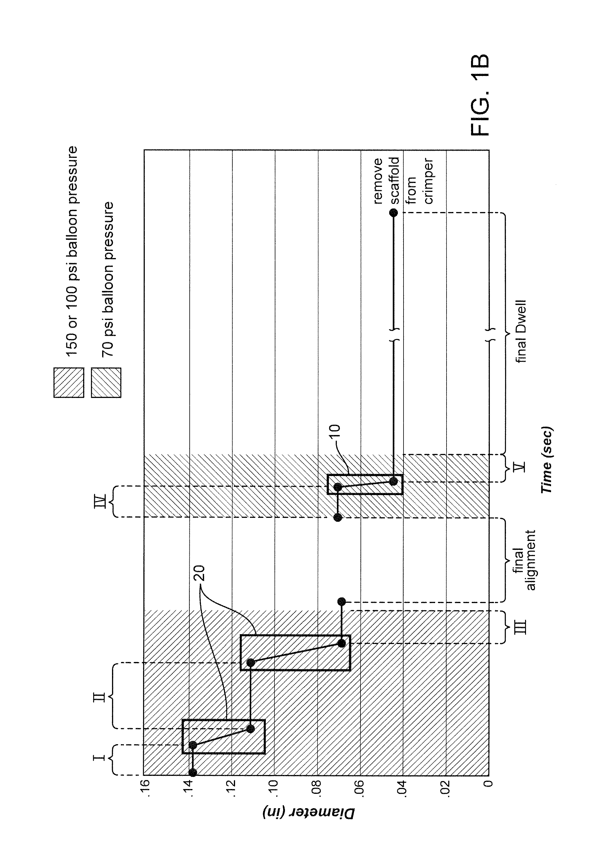
[0014]A crimping method according to the invention includes several crimping steps. For each crimping step where the scaffold is reduced in diameter, a balloon pressure is applied to support the scaffold during the diameter reduction and to work balloon material between scaffold struts. Following these crimping steps, a dwell period occurs in which balloon pressure is maintained to correct any misalignments in scaffold struts, deter further misalignment in subsequent crimping steps, and further work the balloon material between scaffold struts. The dwell period also serves to cause stress relaxation in the viscoelastic material. After one or more initial crimping steps, the partially-crimped scaffold is removed from the crimper head to check alignment on the balloon. This step is referred to as a final alignment, or check of final alignment step in the disclosure. After checking final alignment, the scaffold is returned to the crimper to perform the final crimp. The final diameter reduction is also performed with balloon pressure to urge balloon material between gaps in the scaffold struts before reaching the final crimped diameter. It was found that there was a significant increase in the retention or pull-off force of the crimped scaffold on the balloon when the balloon was pressurized during the crimping steps, i.e., when the scaffold diameter was reduced in size.
[0016]In accordance with these objectives, the invention seeks to both increase a retention force between a balloon and scaffold and reduce the stress relaxation period following crimping by selection of a crimping temperature of about the onset of TG, or slightly above this temperature, but without adversely affecting the scaffold mechanical properties during the crimping process. The material may be a polymer comprising PLLA or PLGA. It has been found that a crimping temperature suited to this purpose is the onset of TG (TG-low) or 5 degrees centigrade above the onset of TG. For this temperature range the stress relaxation due to large deformation caused by crimping would be greatly accelerated, thereby reducing the period of time it takes for radial strength, recoil and other important scaffold properties to stabilize. Thus, the time period from crimping to when scaffold properties stabilize is favorably reduced.
[0022]According to another aspect of the invention, a method for crimping a balloon-expanded scaffold to a balloon includes the steps of providing a tube comprising PLLA characterized by a glass transition temperature range having a lower limit of about TG-low; radially expanding the tube to increase its radial stiffness; forming the scaffold from the radially-expanded tube, including the steps of forming a circumferential series of closed cells having a W-shape and linear link struts connecting the W-shape cells; and crimping the scaffold to the balloon while the scaffold has a crimping temperature of between about TG-low and 5 degrees centigrade above TG-low including maintaining a pressure in the balloon as the scaffold diameter is being reduced in size.

Problems solved by technology

However, at this temperature the stresses built-up in the crimped scaffold can take quite a long time (e.g., up to several weeks) to resolve, i.e., stress relaxation, for room temperature storage conditions after crimping.
The crimping temperature, however, should also not be raised too high to suit this need, because if raised too high memory loss in the material occurs during crimping that causes a loss in radial strength and / or fracture when the scaffold is deployed.

Method used


Image

  • Methods for crimping a polymeric scaffold to a delivery balloon and achieving stable mechanical properties in the scaffold after crimping
  • Methods for crimping a polymeric scaffold to a delivery balloon and achieving stable mechanical properties in the scaffold after crimping
  • Methods for crimping a polymeric scaffold to a delivery balloon and achieving stable mechanical properties in the scaffold after crimping

Examples


examples

[0059]Further details of the FIG. 1A flow process for a 3.5 mm scaffold manufacture and crimping to a delivery balloon will now be discussed. FIG. 1B illustrates in graphical form the crimping portion of the FIG. 1A flow—a graph of scaffold diameter verses time with a balloon pressure of 150 psi or 70 psi applied during the dwell periods and the intermediate pressure step (i.e., crimping between Stage IV and Stage V). The scaffold was crimped using a crimper having film-sheets disposed between the metal crimper blades and the scaffold. This particular type of crimper is discussed in greater detail below.

[0060]As discussed above, the scaffold is formed from a PLLA or PLGA precursor, including a biaxial expansion of the precursor to form a tube, followed by laser cutting the scaffold from the tube. Next, a pre-crimp procedure is performed, which includes placing the scaffold between the balloon markers and aligning the scaffold with the iris of the crimper. Using an anti-static air gu...


PUM

PropertyMeasurementUnit
TGaaaaaaaaaa
crimping temperatureaaaaaaaaaa
temperatureaaaaaaaaaa

Abstract

A medical device-includes a polymer scaffold crimped to a catheter having an expansion balloon. The scaffold is crimped to the balloon by a process that includes inflating the delivery balloon during a diameter reduction to improve scaffold retention. A crimping temperature is maintained at about the onset of glass transition of the polymer material to facilitate more rapid stabilization of mechanical properties in the scaffold following crimping.

Description

BACKGROUND OF THE INVENTION[0001]1. Field of the Invention[0002]The present invention relates to drug-eluting medical devices; more particularly, this invention relates to processes for crimping a polymeric scaffold to a delivery balloon.[0003]2. Background of the Invention[0004]The art recognizes a variety of factors that affect a polymeric scaffold's ability to retain its structural integrity when subjected to external loadings, such as crimping and balloon expansion forces. These interactions are complex and the mechanisms of action not fully understood. According to the art, characteristics differentiating a polymeric, bio-absorbable scaffolding of the type expanded to a deployed state by plastic deformation from a similarly functioning metal stent are many and significant. Indeed, several of the accepted analytic or empirical methods / models used to predict the behavior of metallic stents tend to be unreliable, if not inappropriate, as methods / models for reliably and consistentl...

Claims


Application Information

Patent Timeline
Patent Type & Authority Patents(United States)
IPC IPC(8): A61F2/06B23P11/02
CPCA61M25/1034A61L31/16A61L31/06A61F2/958B23P11/025Y10T29/49865Y10T29/49913Y10T29/49925Y10T29/49927Y10T29/49929A61F2240/001A61F2/9524C08L67/04A61F2/9522B29D23/00B29K2067/043B29K2067/046B29K2995/0082
Inventor WANG, YUNBING
Owner ABBOTT CARDIOVASCULAR
Why Eureka
Try Eureka