Synthetic ripple hysteretic powder converter

a technology of hysteretic powder and ripple, which is applied in the direction of power conversion systems, dc-dc conversion, instruments, etc., can solve the problems of slow overall response of boost converters, rhpz can complicate the stability of loops, and difficult to obtain fast control of boost converters, etc., to reduce the value, size and cost of its passive components.

Active Publication Date: 2014-07-15
QUALCOMM INC
View PDF16 Cites 10 Cited by
  • Summary
  • Abstract
  • Description
  • Claims
  • Application Information

AI Technical Summary

Benefits of technology

[0017]It is an objective of the present invention to provide an inductive boost switching power converter that can operate at high switching frequency therefore allowing a reduction of the value, size, and cost of its passive components.
[0018]It is another objective of the present invention to provide a switching boost power converter that includes an hysteretic or pseudo-hysteretic control circuit by means of a feedback network that generates a signal containing the information of instantaneous output voltage, both from a dc standpoint and from an ac standpoint, and a means of generating a synthetic ripple signal that is proportional and in phase with the inductor current allowing very fast load transient response.
[0019]It is another objective of the present invention to provide a switching boost converter with high efficiency at any load condition by means of control of CCM (Continuous Conduction Mode) mode of operation and DCM (Discontinuous Conduction Mode) mode of operation depending on the load impedance values.

Problems solved by technology

Fast control of boost converters is difficult to obtain in CCM because there is always an intrinsic delay in providing energy to the load since the inductor has to be first charged with current flowing in it.
This RHPZ can complicate the stability of the loop and generally is dealt with by rolling off the loop gain of the switching voltage regulator at relatively low frequency, making the overall response of the boost converter quite slow.
However, as mentioned, these types of control methods do not present high bandwidth and require the adoption of large output capacitors to obtain acceptable load transient responses.
The intrinsic delay of the boost architecture, deriving from the fact that the boost does not supply current to the load while charging the inductor, makes the implementation of an hysteretic approach much more difficult to obtain.
However the proposed architecture presents two major drawbacks: a higher power dissipation because the resistor is placed directly on the power path, and a high output ripple because the resistor is in series to the output capacitor.

Method used


Image

  • Synthetic ripple hysteretic powder converter
  • Synthetic ripple hysteretic powder converter
  • Synthetic ripple hysteretic powder converter

Examples


Embodiment Construction
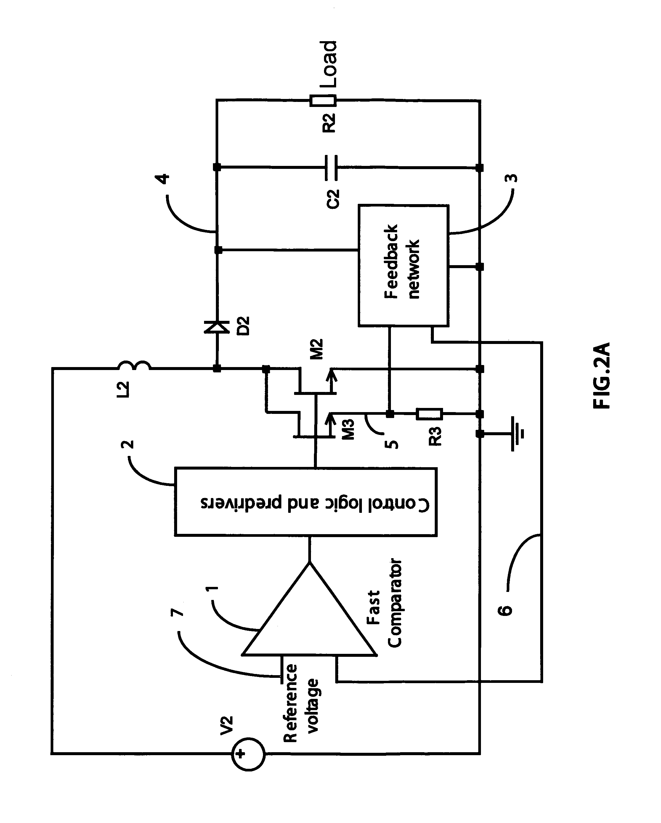
A FIG. 2

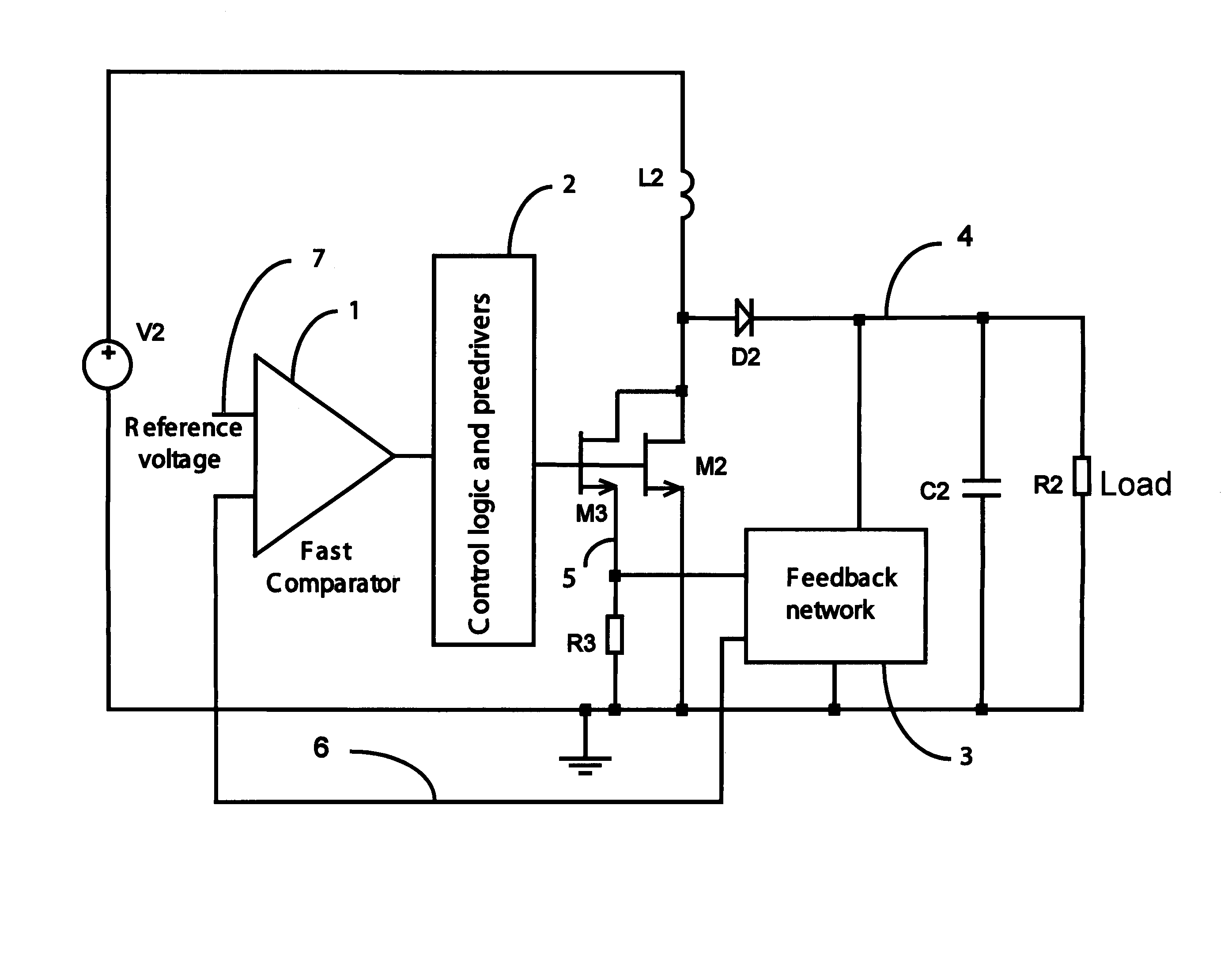
[0059]FIG. 2 is showing the schematic of the synthetic ripple hysteretic boost power converter according to the preferred embodiment of the present invention. FIG. 2 describes a novel approach in which a signal proportional and in phase to the inductor current is fed to a feedback network that generates a synthetic ripple signal to be successively compared to a reference signal to determine the duty cycle and drive signal for the power devices of the boost power converter.

[0060]FIG. 2 describes a transistor M3 in parallel to the main power switch M2, with a resistor R3 in series to its source. The relative size of M3 is only a fraction of the size of the power switch M2. The gate of M3 is in common with M2 so that the two devices are turned on and off in synchronism. M3 operates as a switch in the triode region that reports to its source the voltage appearing to its drain. That voltage across the resistor R3 generates a signal that is proportional to the current in the induc...


PUM


Abstract

A novel switching hysteretic power converter is presented. The converter includes the generation of a synthetic ripple signal and a feedback network to combine a signal in phase with the inductor current with a signal proportional to the regulated output voltage. The presented approach provides a switching boost converter with a much simpler control method with respect to conventional inductive boost power converters. The hysteretic control provides stable operation in all conditions with excellent load and line transient response. Furthermore the hysteretic control allows high frequency switching, reducing the size and cost of the passive components. The presented converter includes the Discontinuous Conduction Mode of operation to achieve very high efficiency at light loads. The presented approach can also be applied to buck switching power converters with excellent performance in terms of transient response, stability, efficiency and operation at high switching frequencies. The approach can be extended also to the hysteretic control of isolated switching flyback converters.

Description

BACKGROUND OF THE INVENTION[0001]1. Field of the Invention[0002]The present invention is in the field of power converters. The present invention is further in the field of semiconductor switching power converters. The present invention further relates to the field of integrated hysteretic control methods for switching power converters and circuits. The implementation is not limited to a specific technology, and applies to either the invention as an individual component or to inclusion of the present invention within larger systems which may be combined into larger integrated circuits.[0003]2. Brief Description of Related Art[0004]Modern electronic applications require power management devices that supply power to integrated circuits or more generally to complex loads. In general, power switching converters are becoming more and more important for their compact size, cost and efficiency. The switching power converters comprise isolated and non isolated topologies. The galvanic isolat...

Claims


Application Information

Patent Timeline
Patent Type & Authority Patents(United States)
IPC IPC(8): H02M3/156
CPCH02M3/156
Inventor MENEGOLI, PAOLOMARINO, FABIO ALESSIO
Owner QUALCOMM INC
Why Eureka
Try Eureka