Apparatus for vaporizing and reforming liquid fuels

a liquid fuel and apparatus technology, applied in the field of gasification systems, can solve the problems of limited vaporization rate, difficult to achieve coke formation, etc., to achieve the effect of reducing the predisposition to coke, facilitating fuel injection, and facilitating mixing

Active Publication Date: 2014-08-05
PRECISION COMBUSTION
View PDF30 Cites 11 Cited by
  • Summary
  • Abstract
  • Description
  • Claims
  • Application Information

AI Technical Summary

Benefits of technology

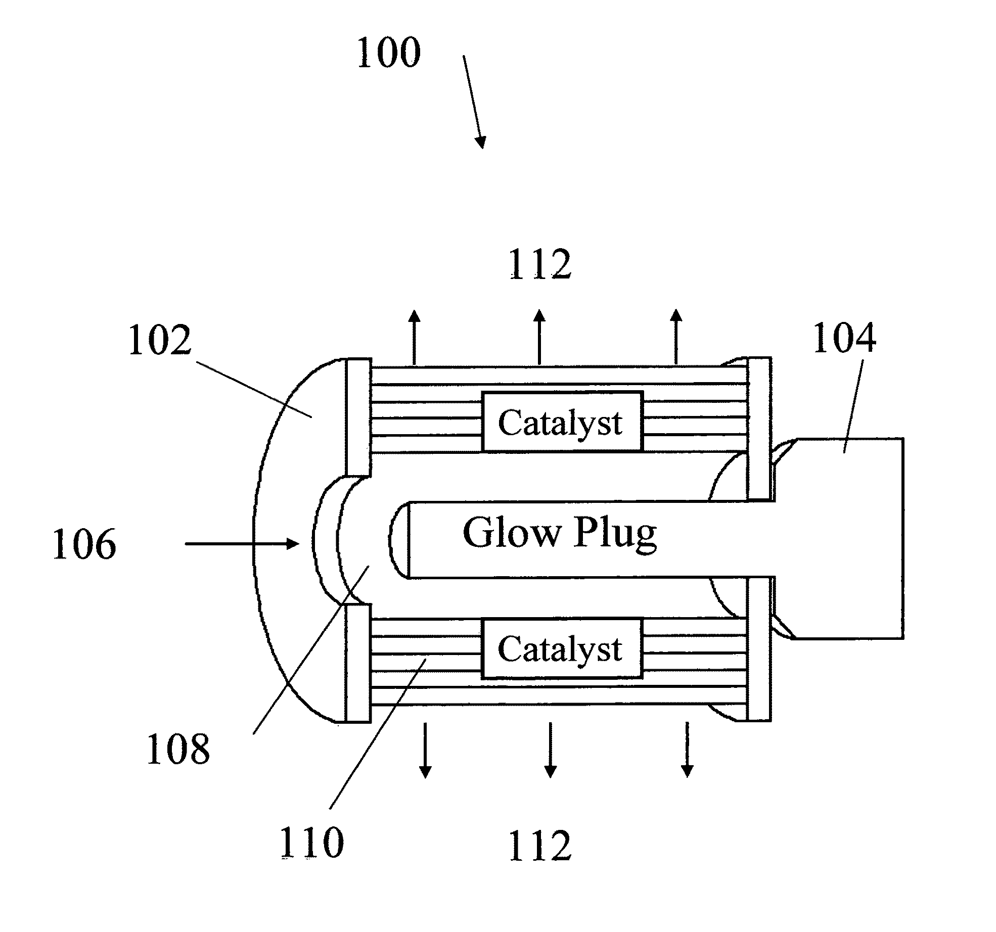
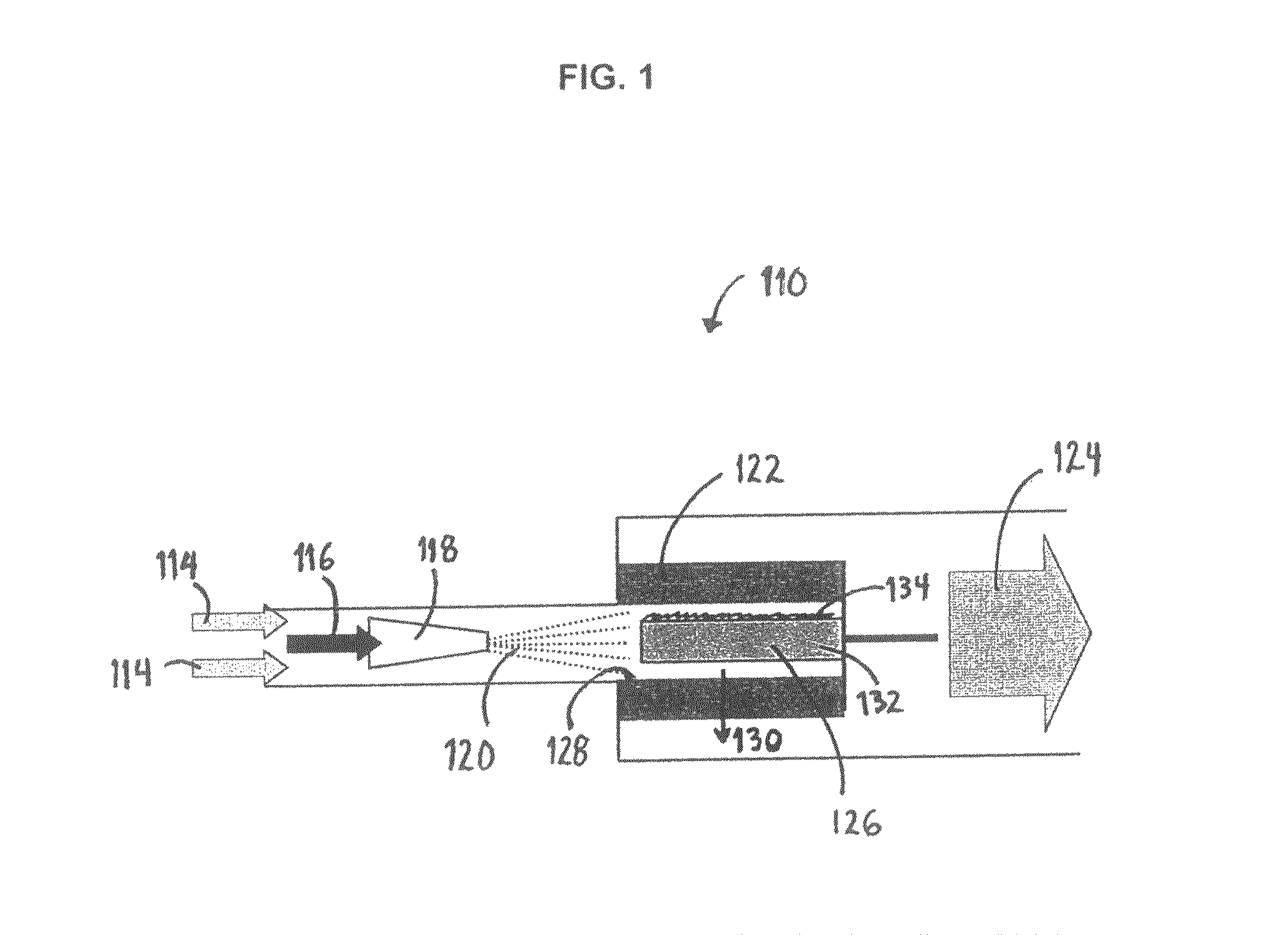
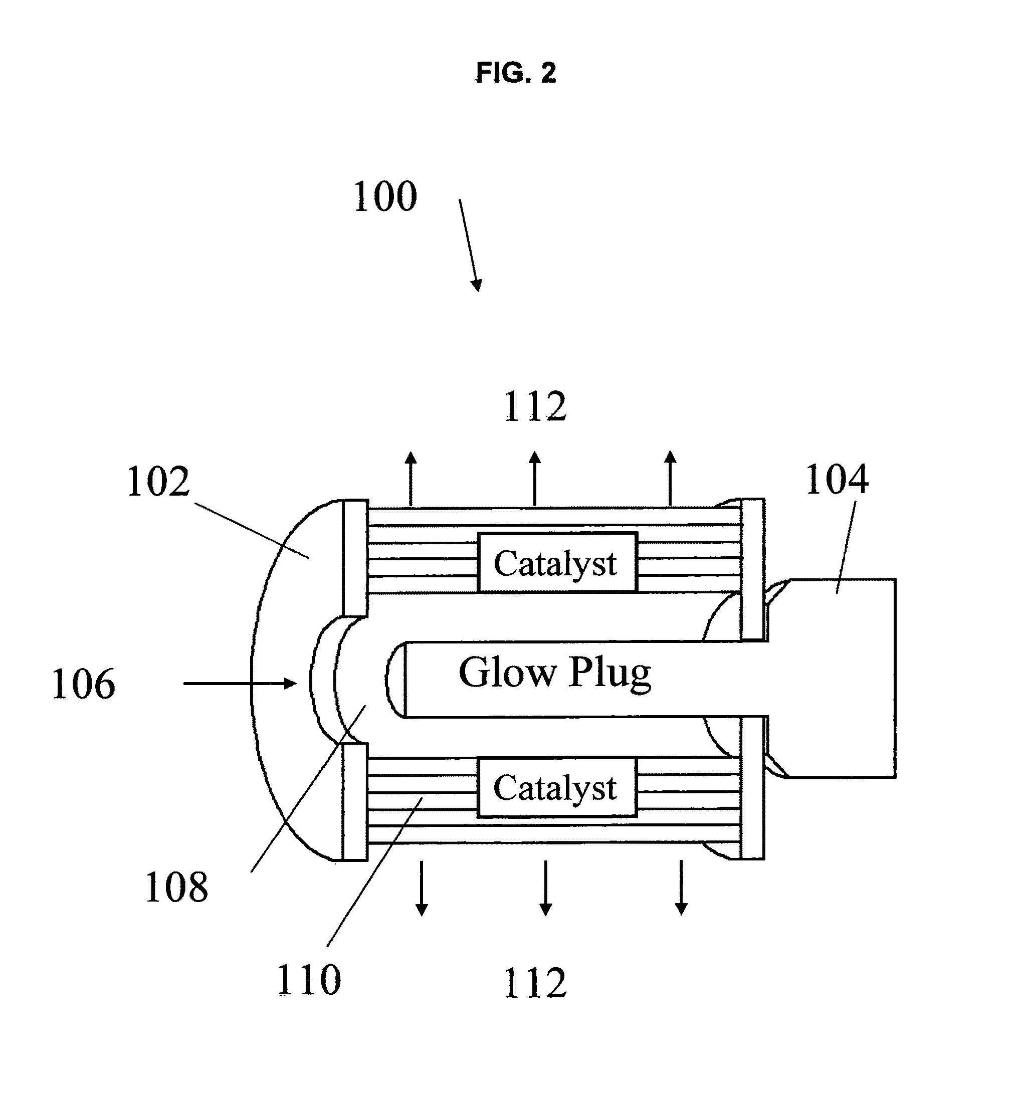
[0021]The present invention is directed to a system and method for vaporizing and reactively converting a liquid fuel into a gasified stream. The method and system of the present invention also provide a means for quickly starting and operating the process at a variety of inlet conditions, including ambient inlet conditions. More particularly, the method includes the steps of atomizing a liquid fuel, mixing the atomized fuel with an oxidizer, preferably, in fuel rich proportions, partially vaporizing the fuel, and passing the resulting stream through a coiled catalytic reactor (also referred to herein as “the catalyst bed”) comprising a coiled metal screen to provide for reforming of the fuel. The catalyst bed is preferably designed for supporting partial oxidation / reforming reactions, preferably at high space velocity, and is integrated with an ignition source to provide for fuel vaporization and ignition of the reforming reaction. The apparatus results in an integrated system comprised of a mixer, a radiation hotbox vaporizer, an igniter, and a catalytic reformer and represents a simplified fuel gasification and reformation approach that provides for rapid start-up (i.e., rapid light-off of the catalytic reactor) and reduces predisposition to coking, especially, with liquid fuels.

Problems solved by technology

One disadvantage of this method is that the rate of vaporization is limited by the rate of heat transfer such that a relatively large surface area is required for fuel vaporization.
Another disadvantage of this method, especially for vaporizing long chain hydrocarbons, is that heating the fuel stream to a vaporization temperature tends to cause fuel decomposition and formation of deposits.
More specifically, coke formation is problematic.
Moreover, preventing deposits from forming within fuel passages in a nozzle used for fuel delivery to a reformer is challenging.
However, large amounts of superheated steam required in this method result in a large heat load for steam production.
However, very fine and uniform droplet size along with homogeneous fuel-air distribution, required to avoid coke formation and obtain temperature / mixture uniformity in the reformer, is difficult to achieve in practical reforming systems.
By virtue of their location required for ignition, these devices are often subject to failure due to the reformer's high operating temperatures.
Inhomogeneities in a fuel-oxidizer mixture are usually detrimental to monolith substrates, because inhomogeneities can lead to localized lean or rich zones causing hot spots or carbon precipitation regions, respectively.
Little opportunity exists for these zones to re-mix within the monolith, because monolith substrates generally have long separated channels.
Thus, monolith substrates are particularly vulnerable.
Vaporization of liquid fuels poses significant problems, especially for fuels with high aromatic content and wide boiling point distribution.
This configuration results in a comparatively low conversion rate of the reactants to the desired products.
Disadvantageously, this process requires a source of external heat at the nozzle to vaporize the liquid fuel; thus the fuel is prone to coking at the nozzle.
Moreover, the solid finned metal catalyst is not designed for thorough mixing.
Additionally, axial flow is not commensurate with satisfactory temperature control or maximization of hydrogen product.

Method used


Image

  • Apparatus for vaporizing and reforming liquid fuels
  • Apparatus for vaporizing and reforming liquid fuels
  • Apparatus for vaporizing and reforming liquid fuels

Examples


Embodiment Construction

[0030]This application is a continuation-in-part of U.S. patent application Ser. No. 11 / 974,988, filed Oct. 16, 2007, which is a continuation in part of U.S. patent application Ser. No. 10 / 902,512, filed Jul. 29, 2004, now abandoned, which claims the benefit of U.S. Provisional Application No. 60 / 491,604, filed Jul. 31, 2003. The aforementioned patent applications are incorporated by reference in their entirety into this description.

[0031]The fuel supplied to the apparatus and process of this invention comprises any liquid fuel, for example, obtained from a petroleum, biomass, or synthetic source. The fuel is typically a liquid at about 21° C. and 1 atmosphere pressure; and preferably, has a normal boiling point in a range from about 200° C. to about 400° C. Generally, the fuel comprises a mixture of paraffinic, cycloaliphatic, and aromatic hydrocarbons. Suitable fuels include without limitation, diesel, kerosene, and jet propulsion fuels, such as JP-8, JP-5, and Jet A, as well as s...


PUM


Abstract

The present invention is an apparatus for the gasification of liquid fuels, involving: (a) a nozzle for atomizing and feeding a liquid fuel into a mixing region; (b) an inlet for feeding an oxidizer into the mixing region; (c) the mixing region for mixing the atomized fuel with the oxidizer; (d) a radiation hot box for vaporizing the liquid fuel, the radiation hot box comprising an ignition source positioned inside coiled catalytic reactor; (e) the coiled catalytic reactor comprising a coiled metal screen providing for a radial flow path from an inner diameter to an outer diameter of the coiled metal screen and providing for a plurality of void volumes in random order along the flow path from the inner diameter to the outer diameter; and (f) an outlet for exiting a gaseous reformate.

Description

CROSS-REFERENCE TO RELATED APPLICATIONS[0001]This application is a continuation-in-part of U.S. patent application Ser. No. 11 / 974,988, filed Oct. 16, 2007 now U.S. Pat. No. 7,976,594, which is a continuation in part of U.S. patent application Ser. No. 10 / 902,512, filed Jul. 29, 2004, now abandoned, which claims the benefit of U.S. Provisional Application No. 60 / 491,604, filed Jul. 31, 2003.FIELD OF THE INVENTION[0002]The present invention is directed to a gasification system (alternatively, “apparatus” or “catalytic reformer) for vaporizing and reforming a liquid fuel, such as diesel fuel. More particularly, the apparatus is designed for vaporization and reforming of a liquid fuel to form a partially-oxidized gaseous reformate, preferably, a mixture of hydrogen and carbon monoxide. Hereinafter, the apparatus is referred to as a “reformer” or as a “gasifier” or as a “pre-reformer.” The terms “reformer” and “gasifier” are applicable in equivalent situations wherein a fuel is converte...

Claims


Application Information

Patent Timeline
Patent Type & Authority Patents(United States)
IPC IPC(8): B01J7/00
CPCB01J8/0214B01J4/002B01J8/0221B01J8/0278B01J8/0285B01J19/26B01J2208/00716C01B3/38C01B3/382C01B2203/0244C01B2203/0255C01B2203/0261C01B2203/0844C01B2203/1047C01B2203/1247C01B2203/1276C01B2203/1288C01B2203/142C01B2203/1604C01B2203/82C10G11/02
Inventor ROYCHOUDHURY, SUBIRLYUBOVSKY, MAXIMBERRY, JONATHAN D.
Owner PRECISION COMBUSTION
Why Eureka
Try Eureka