Firstly, beam detectors may suffer a type I (false positive) error where foreign objects or other particulate matter, such as dust, enters the monitored area and obscure the beam. Beam detectors are generally unable to distinguish between the obscuration caused by particles of interest e.g.
smoke, and obscuration which results from the presence of
foreign body of no interest e.g. a bug flying into the beam.
Secondly, beam detectors may require careful alignment at the time of installation. Such alignment aims to ensure that in
normal conditions, free from particles, light enters the sensor so as to capture the majority of the transmitted beam, and to in turn maximise sensitivity to an obscuration. This calibration may be slow and therefore costly to perform. Moreover, it may need to be repeated as the physical environment changes, for example because of small movements in the structure to which a beam
detector is attached. In some cases, if the intensity of incident light on the detector diminishes quickly this misalignment may also cause a
false alarm.
However, these constraints as well as constraints on the intensity of light sources able to be used as transmitters mean that there may be a need to further enhance the particle detection
system in these respects.
Furthermore, in some cases, a limited electrical power supply is available, especially if the
transmitter unit is powered by a battery.
Accordingly, accommodating these seemingly contradictory requirements of the
system can present problems.
A further problem that may arise in such a system is that a reflective surface may provide one or more unintended light paths between the
transmitter and the receiver, and so interfere with either the recognition of the direct light path, or cause uncontrolled and unintended contributions to the received
signal(s), or both.
Since beam detector components are often mounted just below a substantially flat ceiling, this type of undesired reflection may be common.
Adjacent walls, particularly glazed walls, may also create a similar issue with the additional complication that blinds or open-able windows may be used at various times. However, this issue does not arise as commonly, since it is rarely required that beams are directed in close proximity to walls.
This calibration may be slow and therefore costly to perform.
In some cases, if the intensity of incident light on the detector diminishes quickly this misalignment may also cause a
false alarm.
Since beam detectors are typically mounted to a wall or like flat surface it is generally not possible to get behind the detector in order to use a
line of sight type alignment device.
Also, since detectors are usually mounted at high elevations and in inaccessible locations, the problem of achieving accurate alignment, and the difficulties caused by misalignment, are exacerbated.
The inventors have identified that these methods have several disadvantages, particularly in the case of beam-detection systems.
The conventional systems for powering up the battery-powered equipment are not automatic and, in consequence, may be overlooked when the beam-detection system is installed.
This makes it difficult to confirm that the
light source 102, 202 is active when installed.
In addition, the beam detection systems are often installed at a significant height, requiring scaffolding or a cherry-picker to access the system components.
As a result, it is time-consuming and costly to access and rectify a unit that has inadvertently been left non-operational.
Some of the conventional techniques of activating battery-powered units also interfere with the common requirement that beam-detection systems should avoid arrangements that cause penetrations through the main
enclosure of the unit.
It is often the case that transmitters are designed to be resistant to the entry of dust and
moisture, and the use of manually-operated switches may makes this isolation more difficult and costly to achieve.
A further problem that may arise with beam detectors is that their exposed optical surfaces may become contaminated with
dirt over time.
This can gradually reduce the received
signal with the potential to be raise a
false alarm.
Thus any wavelength selective build up of contaminants on the optical surfaces can be problematic.
It is a problem in the field of video surveillance, and similar fields which have remotely located optical devices (such as cameras), that insects or other
foreign bodies may from time to time land on the exposed surfaces of the optical components of the system and partly or totally obscure the
field of view of the optical components.
Similar problems may also arise in particle detection systems like beam detectors which are exposed to bugs and other
foreign bodies.
However, relative variations in the output intensities of the two light emitters may create faults or false alarms.
This presents its own particular problems, in that it is possible to have multiple transmitters set at vastly different distances from the receiver.
Other disadvantages may also arise, for example, from time to time, an installer may take
advantage of the reliable performance of beam detectors and install a system outside the manufacturer's specifications.
In some cases an installer of the
particle detector may not know of the limits of operation of the receiver for the
light source provided therewith.
In such circumstances an installed
particle detector may operate satisfactorily at initial installation, but sometime following installation, cease to operate correctly.
Over time, changes may occur to the equipment or environment, which gradually alter the received
signal strength due to reasons other than the presence of particles in the beam.
These changes may be caused by, for example, component
ageing, gross alignment drift, or
contamination of optical surfaces.
However, when the system is set up outside these limits, degradation of performance and the associated occurrence of fault conditions may occur prematurely or repeatedly.
The present inventors have realised that this type of filter may not be suitable for use with a beam detector of the type described above.
This provides a risk that a small object such as an
insect on the
transmitter could affect one light path more than the other and so affect the reading of the receiver.
This may induce a false alarm or unnecessary fault condition.
This calibration may be slow and therefore costly to perform.
However, this may not yield optimal results.
Because of these effects, any variation in the alignment of the
smoke detector components can potentially create a large variation in the measured
light intensity level.
The resulting variation in the image intensity as determined by the controller can thus potentially cause the controller to falsely detect smoke.
Also it is not always possible for the controller to make this determination.
In beam detectors an additional problem that may arise is interference from ambient light within the volume being monitored.
This problem is compounded by the conflicting requirement that the light sources of the beam detector should be relatively low powered so that they minimise
power consumption, are eye safe and do not create a visible nuisance.
However, this is inappropriate for a multiple wavelength system as described herein.
However, the fire alarm loop usually only provides a very small amount of DC electrical power for the detector.
To address this problem a separate power supply could be used, but this is costly since standards for
fire safety equipment are onerous, e.g. they require a fully approved and supervised battery backed supply, and fixed mains wiring.
The limited supply of power also limits the
optical power output of the transmitter.
If the
signal to noise ratio of the system degrades too far, the system may experience frequent or continual false alarms.
This is undesirable.
As such these links often add significant cost and potential reliability issues to the alarm system.
However, a problem that can arise in a battery powered component of a
particle detector is that over time, the batteries of the component will become discharged and the component will ultimately fail.
Such failure will potentially require an unscheduled maintenance call out for the device to be repaired and recommissioned.
In a smoke detection application this is particularly problematic as the equipment is used in a life-safety role and faults are required to be rapidly remedied.
The problem can be remedied by performing preventative maintenance but ultimately this may amount to performing unnecessary servicing and replacement of units that have a significant amount of battery life remaining and therefore is costly and wasteful of materials.
Unfortunately, variations in individual battery performance and environmental conditions make simply scheduling routine replacement periods unreliable and potentially wasteful.
One apparent solution to the problem is to equip the component with an indicator of battery state, however this has a
disadvantage of adding cost, and the indicator itself is power consuming which further reduces battery life.
Moreover, it requires regular direct inspection of the indicator on the component which, in the case of a beam detector, may be particularly inconvenient.
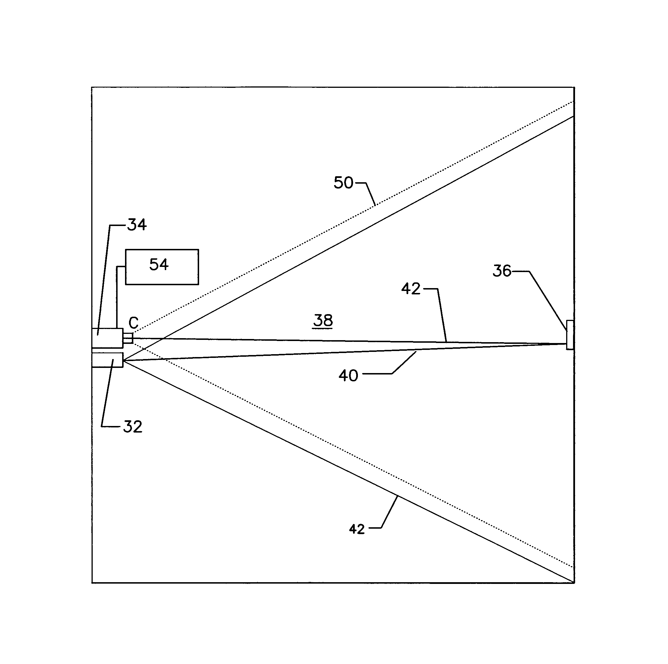
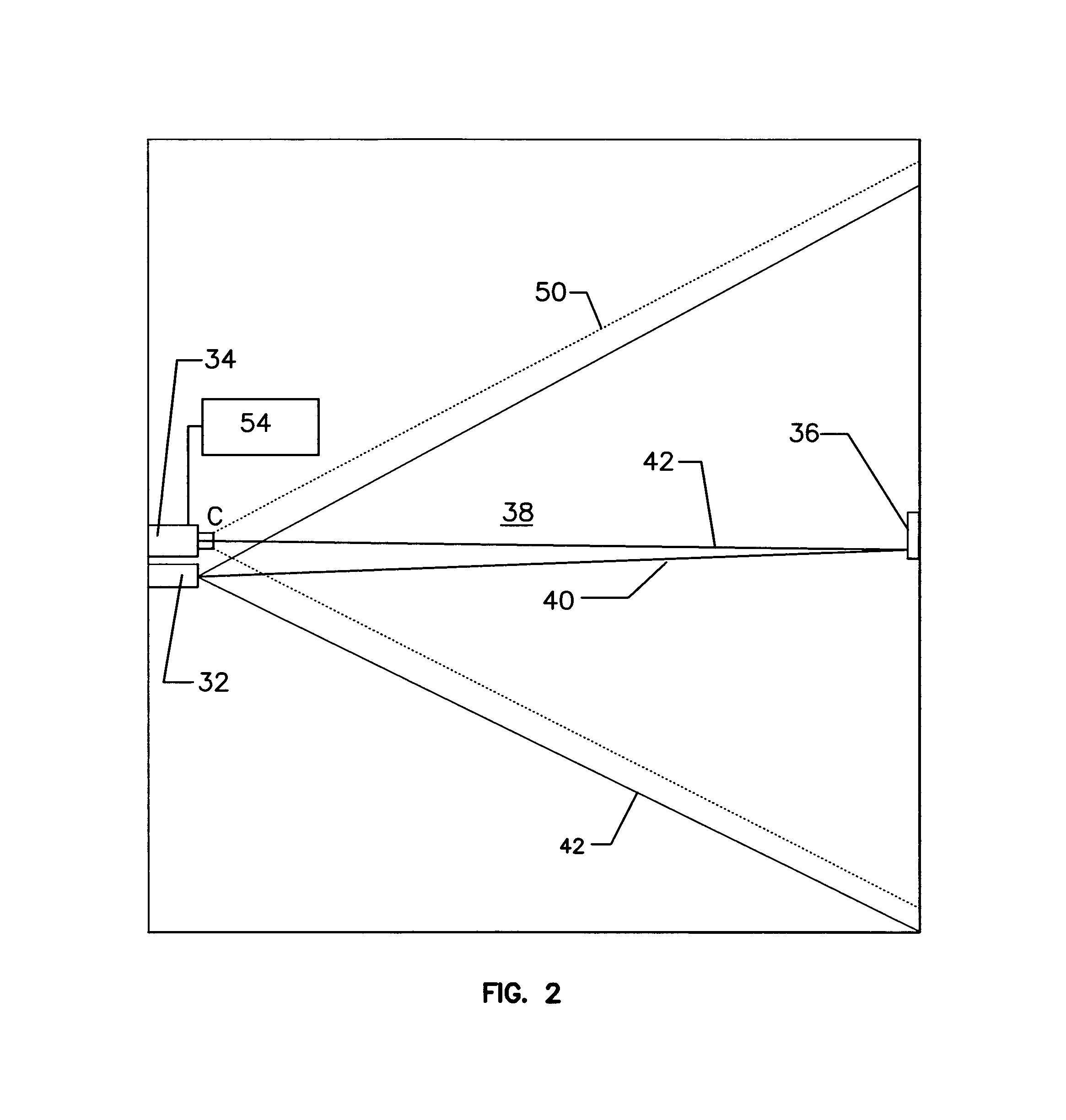
In beam detectors such as that described in relation to FIG. 3 i.e. where a plurality of beam detectors are formed by corresponding transmitter and receiver pairs, such that two or more beams either intersect or pass through a common region of air, sufficiently close to each other that their points of intersection can be mapped to addresses within the region being monitored, a problem may arise in that any one of the subsystems may be affected by environmental conditions or system problems that do not affect the other subsystem.
Such issues generally force a reduction in achievable sensitivity or increase the rate of unwanted false alarms.

