Adaptive on-time control for power factor correction stage light load efficiency

a technology of power factor and light load, applied in the direction of electric variable regulation, process and machine control, instruments, etc., can solve the problems of compromising the cost and power density of the complete power converter, significant complexity, size and weight, etc., and achieve the effect of overall high efficiency

Active Publication Date: 2014-08-12
VIRGINIA TECH INTPROP INC
View PDF8 Cites 25 Cited by
  • Summary
  • Abstract
  • Description
  • Claims
  • Application Information

AI Technical Summary

Benefits of technology

[0008]It is therefore an object of the present invention to provide a PFC stage for a power converter that can maintain high efficiency comparable to full load efficiency of a constant high frequency, variable on-time PFC stage over an extremely wide load range.
[0009]It is another object of the invention to provide a PFC stage for a power converter that can maintain high efficiency over an extreme load range in a sufficiently simple manner to allow significant improvements in power density at low cost.
[0011]In accordance with another aspect of the invention, a power converter circuit is provided comprising a switching circuit configured to conduct pulses of a cyclically varying voltage to a filter / inductor, an output for delivering a predetermined voltage developed by said filter / inductor to a DC / DC converter or a load, a controller for controlling the switching circuit to determine an on-time duration and an off-time duration in accordance with a current delivered to the DC / DC converter or load at a desired voltage, wherein the controller determines the off-time to establish one of a continuous conduction mode or a discontinuous conduction mode for respective pulses of the cyclically varying voltage in accordance with a magnitude of current and wherein, during discontinuous conduction mode, the controller controls the switching circuit such that the off-time includes periods when substantially zero current flows through said filter / inductor and frequency of the pulses is thereby reduced the said current is reduced.

Problems solved by technology

Further, the power converter often represents a significant fraction of the cost of the electronics in such a device and the space and weight thereof may be comparable to the electronics themselves.
On the other hand, depending on the noise magnitude and frequencies present in switching noise that may be generated, the EMI filter stage may be of significant complexity, size and weight and may thus compromise cost and power density of the complete power converter.
However, the PFC stage which generally provides AC to DC conversion and the regulator stage remain a significant contributors to operating losses in power converters.
The principal difficulty in achieving overall high efficiency arises when the load to which power is to be supplied varies more widely, as is particularly the case for modern semiconductor digital processors, logic circuits and memories which have recently become capable of extremely fast cycle times and high clock frequencies.
As is known, an ideal transistor operated in a digital or binary mode, consumes power only during switching transitions and thus higher clock rates imply greater power consumption, even in ideal devices, while state-of-the-art semiconductor devices often operate in modes which are far from ideal and consume significant power in each of the binary states as well as during switching transitions.
However, in PFC circuits developed to date, while capable of acceptable efficiency at full or near-full load by operating at a high, constant switching frequency using variable pulse width, that efficiency cannot be maintained at medium or light load where switching losses at the constant high frequency become dominant.
However, it is increasingly being required that very high efficiency be maintained over the entire potential load range of the circuit(s) to which power is being supplied and it has been found that simply switching from one mode of operation to another mode of operation is inadequate to maintain a sufficiently high efficiency over the entire load range.
Further, attempts to achieve some blending of modes of operation that may have been attempted to date have been similarly unsuccessful in achieving significant efficiency improvement while involving greatly increased complexity to the point of compromising power density, cost and weight of the power converter.

Method used


Image

  • Adaptive on-time control for power factor correction stage light load efficiency
  • Adaptive on-time control for power factor correction stage light load efficiency
  • Adaptive on-time control for power factor correction stage light load efficiency

Examples


Embodiment Construction

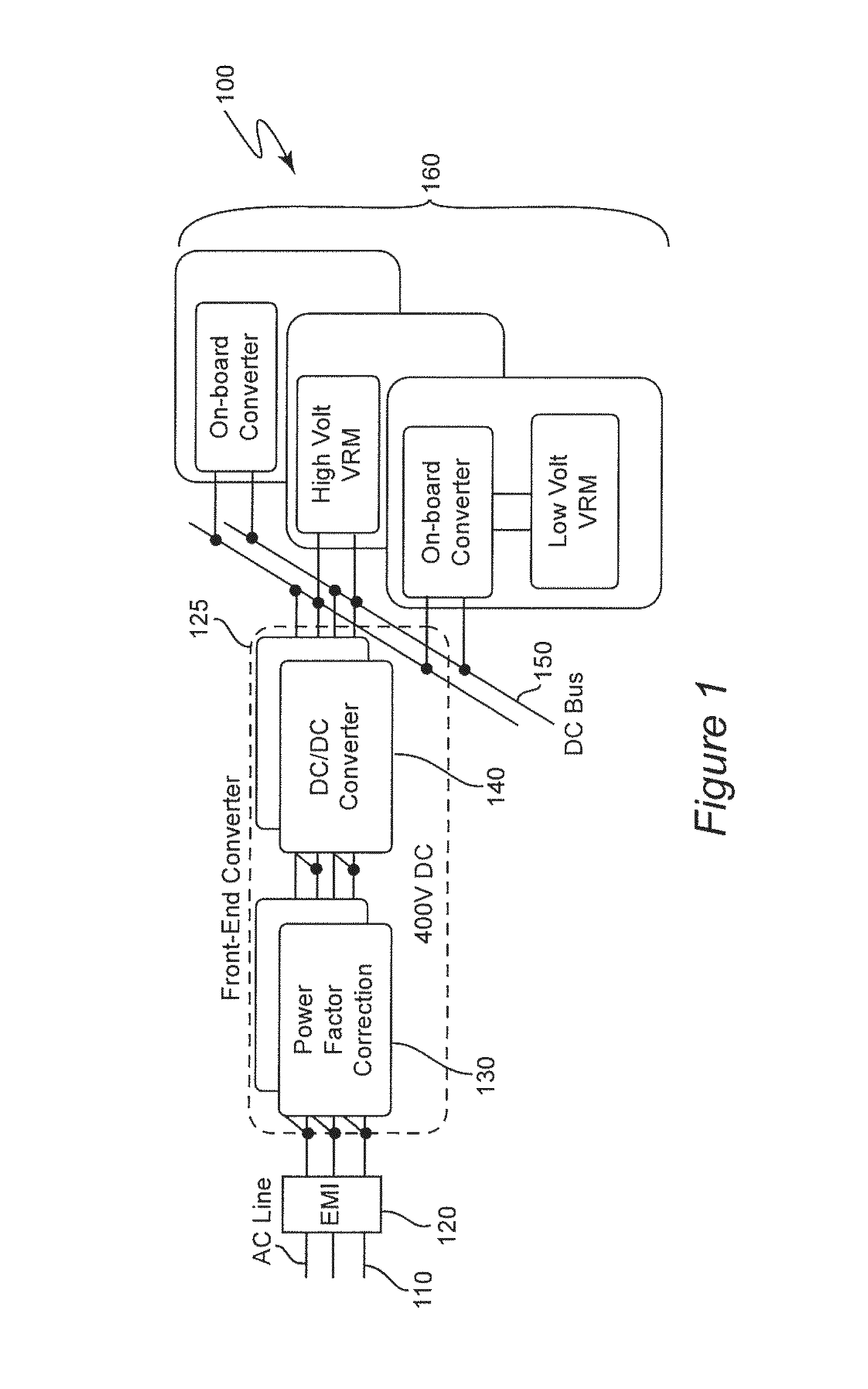
[0036]Referring now to the drawings, and more particularly to FIG. 1, there is shown a generalized high-level block diagram of an AC-DC converter 100 and its application to providing power to one or more systems within one or more electronic devices. AC power, for example, is initially provided from an AC distribution system 110 of one or more phases, three-phase power being illustrated as an example. It should be understood that power could alternatively be supplied from a DC source, such as a battery or DC generator such as a solar array. As alluded to above, an EMI filter 120 is generally provided to reduce noise from the front-end converter 125 and / or the load from being reflected back to the power source and / or radiated to the environment from which it could affect other devices or the power source, itself, such as by causing excess heating in a battery.

[0037]The front-end converter 125 includes a power factor correction (PFC) circuit 130 that develops DC power of approximately...


PUM


Abstract

Light load efficiency of a power factor correction circuit is improved by adaptive on-time control and providing for selection between a continuous conduction mode and a discontinuous conduction mode wherein the discontinuous conduction mode increases time between switching pulses controlling connection of a cyclically varying voltage to a filter / inductor that delivers a desired DC voltage and thus can greatly reduce the switching frequency at light loads where switching frequency related losses dominate efficiency. The mode for controlling switching is preferably selected for each switching pulse within a half cycle of the cyclically varying input voltage. A multi-phase embodiment allows cancellation of EMI noise at harmonics of the switching frequency and adaptive change of phase angle allows for cancellation of dominant higher order harmonics as switching frequency is reduced.

Description

CROSS-REFERENCE TO RELATED APPLICATIONS[0001]This application claims benefit of priority of U.S. Provisional Application 61 / 364,842, filed Jul. 16, 2010, which is hereby incorporated by reference in its entirety.FIELD OF THE INVENTION[0002]The present invention generally relates to power supply and power conversion circuits and, more particularly, to power factor correction circuits generally included therein and techniques for improving efficiency thereof over the load range for power supplied thereby.BACKGROUND OF THE INVENTION[0003]Many electrical and electronic devices, particularly industrial and consumer electronics devices require direct current (DC) power for operation although such power may be ultimately generated and distributed over a power grid as alternating current (AC) power. In many such devices, particularly those including relatively powerful or high performance processors, logic circuits and / or memories, the required DC voltage(s) must be closely regulated. There...

Claims


Application Information

Patent Timeline
Patent Type & Authority Patents(United States)
IPC IPC(8): G05F1/70
CPCH02M1/4216H02M1/4225H02M2001/0032Y02B70/126Y02B70/16H02M1/44Y02B70/10Y02P80/10H02M1/0032H02M3/1586
Inventor LI, QIANLEE, FRED C.XU, MINGWANG, CHUANYUN
Owner VIRGINIA TECH INTPROP INC
Why Eureka
Try Eureka