Magnetic material and motor using the same

a technology of magnetic materials and motors, applied in the direction of magnetic materials, inductance/transformers/magnets, magnetic bodies, etc., can solve the problems of reducing coercive force, various types of defects, and not verifying the presence of fluorine in the main phase, etc., to achieve high coercive force, low iron loss, and high magnetic flux density

Inactive Publication Date: 2014-09-02
HITACHI LTD
View PDF13 Cites 3 Cited by
  • Summary
  • Abstract
  • Description
  • Claims
  • Application Information

AI Technical Summary

Benefits of technology

[0029]A phase containing a group 17 element such as fluorine is formed in a magnetic powder or an iron powder constituted of a light rare earth element and iron, while the crystal orientation is being controlled, and the powder is heat treated and molded, thereby providing the magnetic powder achieving a high coercive force and a high magnetic flux density; and application of moldings obtained by solidifying the powder to rotating machines can provide a low iron loss and a high induced voltage, and the moldings can be applied to magnetic circuits necessitating a high energy product, including various types of rotating machines and voice coil motors of hard discs.

Problems solved by technology

However, the disclosed SmFeF-based material has a low curie point of 155° C. and an unknown magnetization value, and no analysis revealing that fluorine is present in its main phase is disclosed.
Even if fluorine is detected by an analysis of a whole sample having been subjected to a fluorination treatment in the analysis of fluorine after the fluorination treatment, the presence of fluorine in the main phase has not been verified.
Even if a main phase contains fluorine, since the fluorination treatment progresses from the surface of the main phase, a phase having a high fluorine concentration in the vicinity of the surface and a phase having a low fluorine concentration in the vicinity of the center are formed, and the difference in the crystal orientation between these phases different in the fluorine concentration causes various types of defects and a decrease in the coercive force.
Therefore, no practical permanent magnetic material cannot be provided unless the crystal orientation difference is controlled.
Since such a heavy rare earth element is expensive and rare, the decrease in heavy rare earth elements poses a problem from the viewpoint of the environmental protection.
Since a Sm2Fe17N-based magnet cannot be sintered and generally used as bond magnets, it has a drawback in the performance.

Method used


Image

  • Magnetic material and motor using the same
  • Magnetic material and motor using the same
  • Magnetic material and motor using the same

Examples


example 1

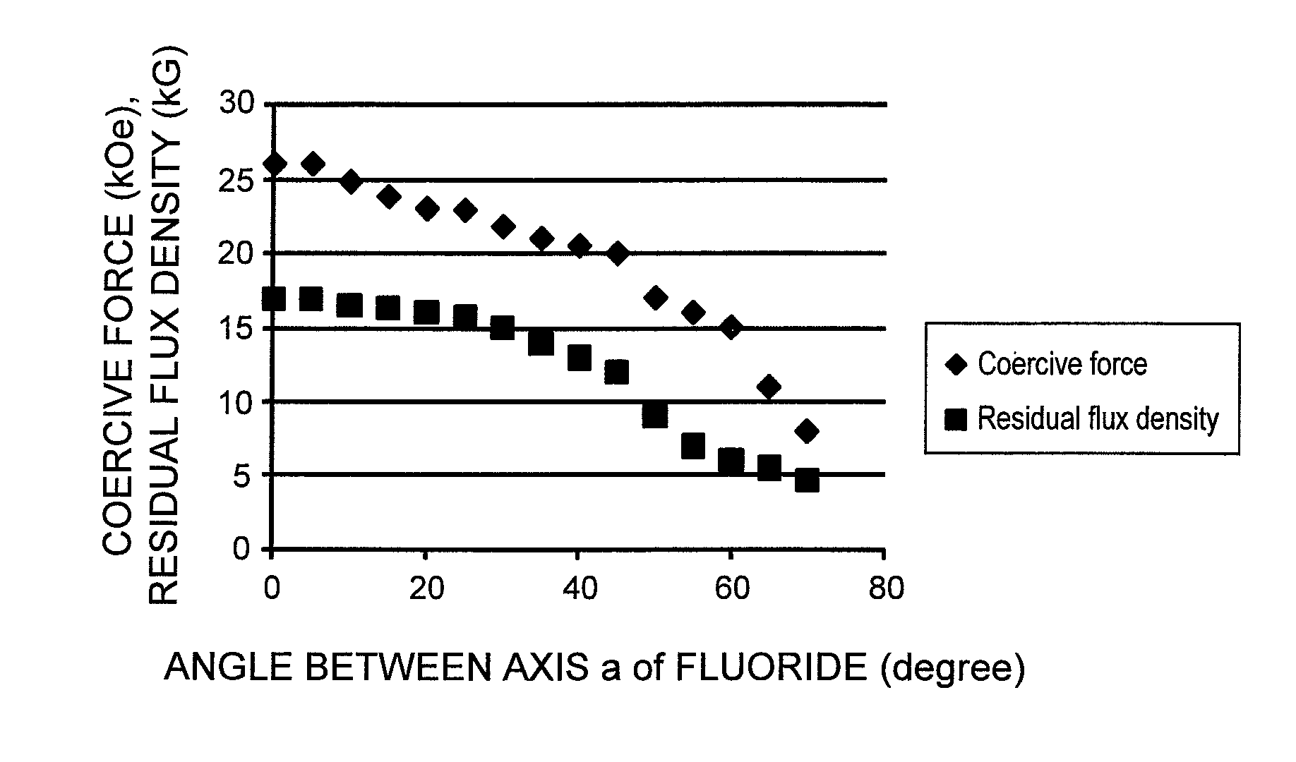
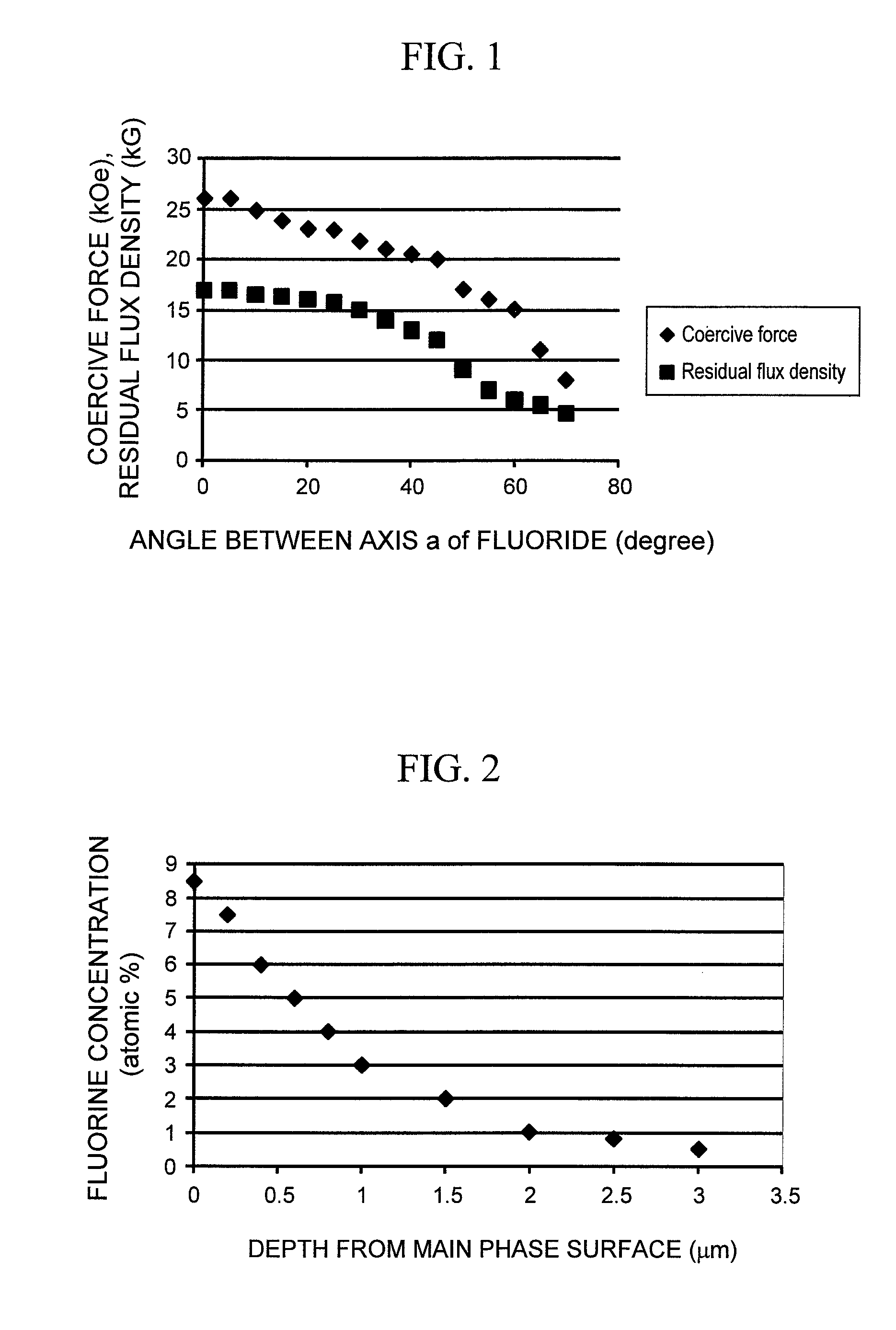
[0066]In the present Example, a fabrication method of a magnetic material which has a phase of the central portion having a low fluorine concentration and a phase of the surface having a high fluorine concentration, and has a crystal orientation difference between the both of 45° or less in average, and a magnet using the magnetic material will be described.

[0067]In order to fabricate a NdFe12F magnet, a master alloy of Nd and iron are melted in vacuum so that the atomic ratio of Nd and Fe becomes 1:12. After the melting and cooling are repeated several times in order to homogenize the composition of the master alloy, the composition is again melted and quenched to form a foil piece of about 100 μm in thickness, which thereafter is pulverized in a hydrogen atmosphere. The pulverized powder has an average powder diameter of 10 to 100 μm.

[0068]The pulverized powder and an ammonium fluoride powder are mixed in an alcohol solvent, charged in a vessel with stainless balls whose surface i...

example 2

[0077]In the present Example, a fabrication method of a magnetic material in which the crystal orientation difference inside the magnetic powder can be made 45° or less, and magnetic characteristics of a magnet fabricated thereby will be described.

[0078]100 g of a Sm2Fe17N3 magnetic powder having a grain diameter of 1 to 10 μM is mixed with 100 g of ammonium fluoride powder. The mixed powder is charged in a reaction vessel, and heated by an external heater. The ammonium fluoride is thermally decomposed by heating, and NH3 and a fluorine-containing gas are generated. Through the fluorine-containing gas, some of N atoms in the magnetic powder start to be replaced with F (fluorine) at 50 to 600° C. In the case of the heating temperature of 200° C., a part of N is displaced with F, and Sm2Fe17(N, F)3 grows in which fluorine and nitrogen are disposed at interstitial positions in a Th2Zn17 or Th2Ni17 structure. By setting the cooling rate after the retained heating at 1° C. / min, some of N...

example 3

[0095]In the present Example, a fabrication process of a magnetic material in which a vapor-deposited Fe grain and a SmF-based alcohol solution are used; the fluorine concentration is different between the central portion and the surface and the difference in the crystal orientation is 45° or less in average, and magnetic characteristics of a magnet fabricated thereby will be described.

[0096]A vapor-deposition source is disposed in a vacuum vessel and Fe is evaporated. The vacuum degree is 1×10⁻⁴ Torr or lower; and Fe is evaporated in the vessel by resistance heating to fabricate a grain of 100 nm in grain diameter. An alcohol solution containing compositional components of SmF2-3 is applied on the Fe grain surface, and dried at 200° C. to thereby form a fluoride film of 1 to 10 nm in average film thickness on the Fe grain surface. The Fe grain coated with the fluoride film is mixed with ammonium fluoride (NH4F), and heated by an external heater. The heating temperature is 200° C.; ...


PUM

PropertyMeasurementUnit
temperatureaaaaaaaaaa
curie pointaaaaaaaaaa
angleaaaaaaaaaa

Abstract

Characteristics of a magnetic material are improved without using a heavy rare earth element as a scarce resource. By incorporating fluorine into a magnetic powder and controlling the crystal orientation in crystal grains, a magnetic material securing magnetic characteristics such as coercive force and residual flux density can be fabricated. As a result, the resource problem with heavy rare earth elements can be solved, and the magnetic material can be applied to magnetic circuits that require a high energy product, including various rotating machines and voice coil motors of hard discs.

Description

BACKGROUND OF THE INVENTION[0001]1. Field of the Invention[0002]The present invention relates to a magnetic material using no heavy rare earth elements, and a motor using the magnetic material.[0003]2. Background Art[0004]Patent Documents 1 to 5 disclose conventional rare earth-sintered magnets containing a fluoride or an oxy-fluoride. Patent Document 6 discloses mixing a rare earth fluoride fine powder (1 to 20 μm) and a NdFeB powder. A Brazilian Patent of Patent Document 7 describes an example of Sm2Fe17 being fluorinated.[0005]Patent Document 1: JP Patent Publication (Kokai) No. 2003-282312A[0006]Patent Document 2: JP Patent Publication (Kokai) No. 2006-303436A[0007]Patent Document 3: JP Patent Publication (Kokai) No. 2006-303435A[0008]Patent Document 4: JP Patent Publication (Kokai) No. 2006-303434A[0009]Patent Document 5: JP Patent Publication (Kokai) No. 2006-303433A[0010]Patent Document 6: U.S. Patent No. 2005 / 0081959[0011]Patent Document 7: Brazilian Patent No. 9701631-4A[00...

Claims


Application Information

Patent Timeline
Patent Type & Authority Patents(United States)
IPC IPC(8): H01F1/00H01F1/058
CPCH01F1/0555H01F41/0293H01F1/0575H01F1/058H01F1/0596H01F1/0009
Inventor KANDA, TAKAYUKIKOMURO, MATAHIROSUZUKI, HIROYUKISATSU, YUICHI
Owner HITACHI LTD
Why Eureka
Try Eureka