
Conductive polymer coating for wet electrolytic capacitor

a technology of conductive polymer and electrolytic capacitor, which is applied in the manufacture of electrolytic capacitors, liquid electrolytic capacitors, electrolytic capacitors, etc., can solve the problems of low unit cell voltage of this type of capacitor and easy detachment of coatings

Active Publication Date: 2014-09-02
KYOCERA AVX COMPONENTS CORP
View PDF59 Cites 9 Cited by
  • Summary
  • Abstract
  • Description
  • Claims
  • Application Information

AI Technical Summary

Benefits of technology

This patent is about a type of wet electrolytic capacitor that uses a micro-roughened metal substrate with pits and a conductive polymer coating made of nanoparticles. The nanoparticles are made of a substituted polythiophene. The technical effect is to improve the performance and reliability of wet electrolytic capacitors by using a new type of electrolyte that enhances the stability and functionality of the capacitor.

Problems solved by technology

The unit cell voltage in this type of capacitor is generally low due to the inevitable decomposition of the electrolyte at high voltage.
Unfortunately, however, the coatings can become easily detached under certain conditions, such as in the presence of aqueous electrolytes.

Method used


Image

  • Conductive polymer coating for wet electrolytic capacitor
  • Conductive polymer coating for wet electrolytic capacitor
  • Conductive polymer coating for wet electrolytic capacitor

Examples


example 1

[0062]Initially, 100 pieces of cylindrical tantalum cans with a size of 18.3 mm (length)×9.1 mm (internal diameter) were sandblasted with a JetStreem Blaster II (SCM System, Inc.). The sandblasting media was black silicone carbide grit having a size of 63 to 106 μm). The media flow rate was 0.5 grams per second via a 3.2-millimeter blasting nozzle. All pieces of cylindrical tantalum cans were sandblasted to a control level 10.7 millimeters (from potential 18.3 millimeters) using appropriate ferrules. The sandblasting time was 20 seconds. These samples were then degreased in water with surfactants in an ultrasonic bath for 5 minutes, rinsed 3 times in deionized water, and then dried at a temperature of 85° C. for 5 minutes. A conductive polymer coating was applied to the microroughened surface of the tantalum cans by dipping the anode into a dispersed poly(3,4-ethylenedioxythiophene) having a solids content 1.1% (Clevios™ K, H.C. Starck). The tantalum cans were filled to the control ...

example 2

[0063]100 pieces of cylindrical tantalum cans were sandblasted as described in Example 1. Thereafter, a conductive polymer coating was formed by dipping the cans into a butanol solution of iron (III) toluenesulfonate (Clevios™ C, H.C. Starck) for five (5) minutes and subsequently into 3,4-ethylenedioxythiophene (Clevios™ M, H.C. Starck) for five (5) minutes. The cans were drained using a vacuum for up to one (1) minute and were put into a drying oven for 45 minutes at 30° C. The resulting structure of poly(3,4-ethylenedioxythiophene) was washed in methanol to remove reaction by-products for five (5) minutes and the tantalum cans were put into a drying oven for five (5) minutes at 85° C. This polymerization cycle was repeated (4) times.

[0064]Once formed, 10 samples of the cathodes of Examples 1 and 2 were then tested for capacitance and ESR in the manner described above. Furthermore, the capacitance and ESR of the samples was also measured after “storage testing” and “temperature / pre...


PUM

PropertyMeasurementUnit
average diameteraaaaaaaaaa
diameteraaaaaaaaaa
thicknessaaaaaaaaaa

Abstract

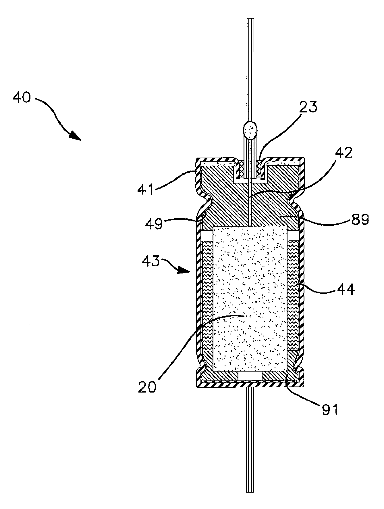
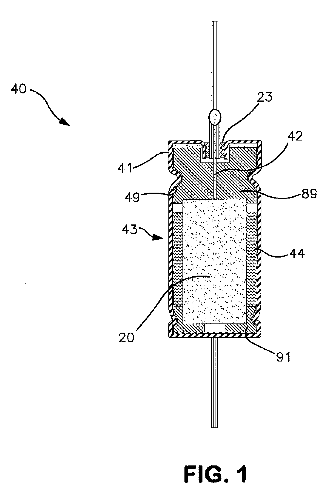
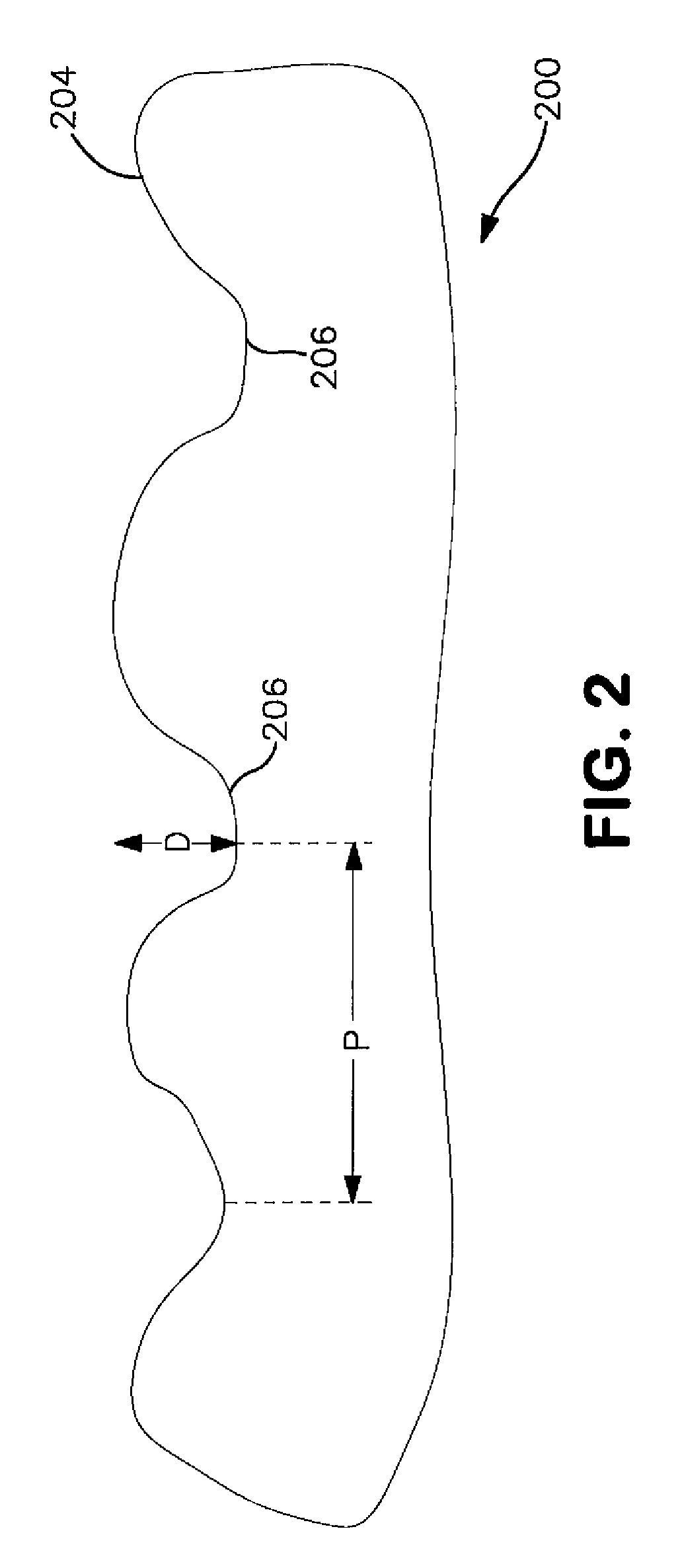
A wet electrolytic capacitor including a porous anode body containing a dielectric layer, a cathode containing a metal substrate on which is disposed a conductive polymer coating, and an electrolyte is provided. The conductive polymer coating is in the form of a dispersion of particles having an average diameter of from about 1 to about 500 nanometers, in some embodiments from about 5 to about 400 nanometers, and in some embodiments, from about 10 to about 300 nanometers. The relatively small size of the particles used in the coating increases the surface area that is available for adhering to the metal substrate, which in turn improves mechanical robustness and electrical performance (e.g., reduced equivalent series resistance and leakage current). Another benefit of employing such a dispersion for the conductive polymer coating is that it may be able to better cover crevices of the metal substrate and improve electrical contact.

Description

CROSS REFERENCE TO RELATED APPLICATIONS[0001]The present application claims benefit of U.S. Provisional Application Ser. No. 61 / 383,438 having a filing date of Sep. 16, 2010.BACKGROUND OF THE INVENTION[0002]Wet capacitors are increasingly being used in the design of circuits due to their volumetric efficiency, reliability, and process compatibility. Wet capacitors typically have a larger capacitance per unit volume than certain other types of capacitors, making them valuable in high-current, high power and low-frequency electrical circuits. One type of wet capacitor that has been developed is a wet electrolytic capacitor that includes a valve metal anode, a cathode, and a liquid electrolyte. The unit cell voltage in this type of capacitor is generally higher due to the formation of a dielectric metal oxide film over the anode surface. Wet electrolytic capacitors tend to offer a good combination of high capacitance with low leakage current. Another type of wet capacitor is a wet symm...

Claims


Application Information

Patent Timeline
Patent Type & Authority Patents(United States)
IPC IPC(8): H01G9/04H01G9/145
CPCH01G9/0425H01G9/06H01G9/0036H01G9/145H01G9/028
Inventor BILER, MARTINDREISSIG, DIRK H.PRIBAN, FRANTISEKPETRZILEK, JAN
Owner KYOCERA AVX COMPONENTS CORP
Learn More