Fuel system inerting

a fuel system and inerting technology, applied in the field of fuel systems, can solve the problems of affecting the reliability affecting the efficiency affecting the operation of fuel system components, so as to improve the regeneration efficiency of condenser-evaporator, increase the temperature difference between the condenser and the evaporator, and improve the regeneration efficiency

Active Publication Date: 2014-09-09
AIRBUS OPERATIONS LTD
View PDF7 Cites 37 Cited by
  • Summary
  • Abstract
  • Description
  • Claims
  • Application Information

AI Technical Summary

Benefits of technology

[0010]A further aspect of the invention provides a method of reducing the carbon dioxide content of oxygen depleted air (ODA) produced by a catalytic inerting device for inerting a fuel tank ullage atmosphere, the method comprising separating carbon dioxide from the ODA gas before feeding the carbon dioxide depleted ODA gas to the fuel tank.
[0028]Alternatively, the evaporator water reservoir and the condenser water reservoir may be fluidically coupled by an upper conduit extending between the upper parts of the reservoirs and a lower conduit extending between the lower parts of the reservoirs. By providing the condenser and evaporator as separate reservoirs, the temperature differential between the condenser and evaporator can be increased leading to improved regeneration efficiency. A pump may be required to move the water between the two reservoirs.

Problems solved by technology

The ullage can contain reactive components, such as oxygen and / or fuel vapours, which can be a potential fire / explosion hazard.
Water is an unavoidable contaminant in fuel but it can affect fuel system component reliability and lead to operational delays and increased maintenance activities.
Accordingly, some water will inevitably be present within the fuel tanks.
The carbon dioxide within the ODA gas generated by the catalytic inerting system poses a problem because when it dissolves in the water in the fuel tanks it forms carbonic acid, which is corrosive and presents a threat to materials and structures in the fuel tank.

Method used


Image

  • Fuel system inerting
  • Fuel system inerting
  • Fuel system inerting

Examples


Embodiment Construction

)

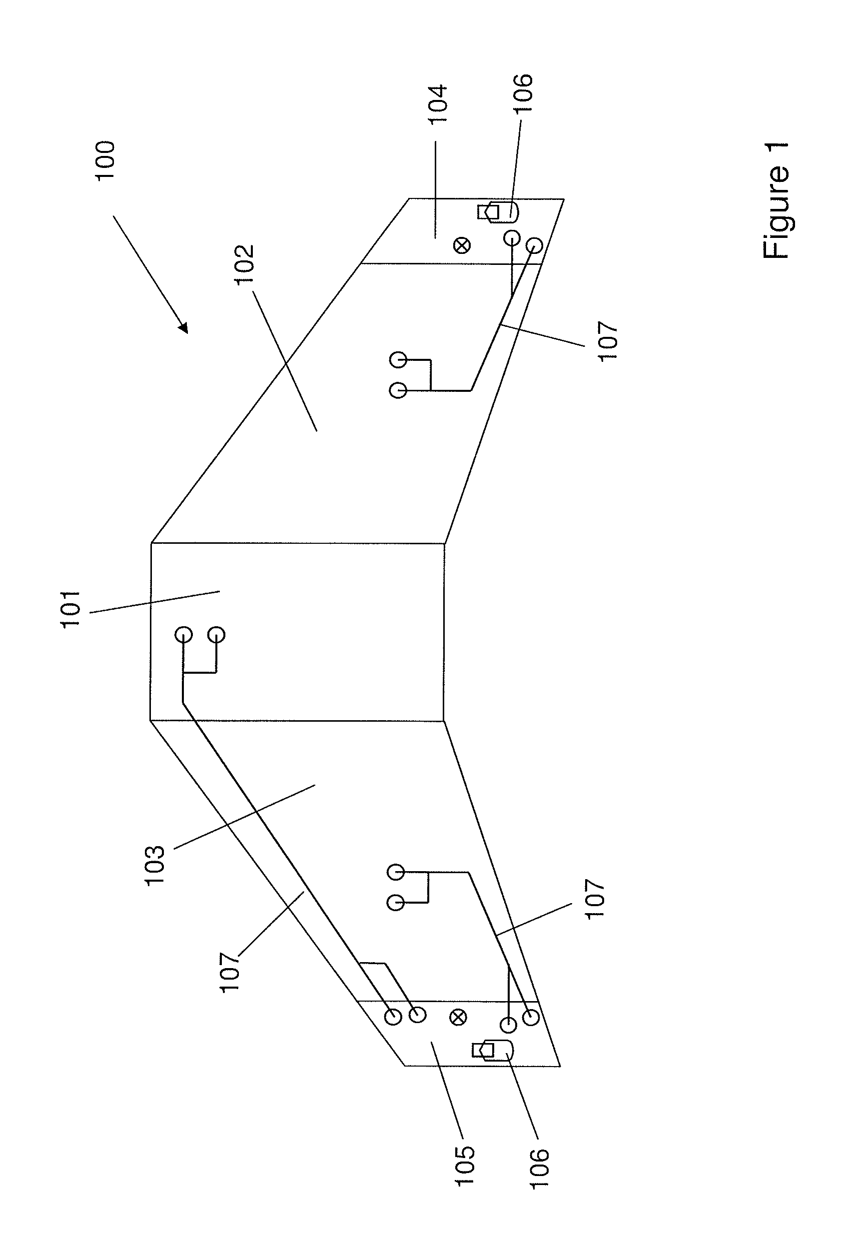
[0036]FIG. 1 illustrates a general wing fuel tank architecture 100 of an aircraft having a three-tank configuration. The fuel tank architecture 100 includes a centre fuel tank 101, a right wing fuel tank 102, and a left wing fuel tank 103. The fuel tanks 101, 102 and 103 are ventilated by means of wing tip vent tanks 104, 105 each having a NACA duct assembly 106 including a NACA vent, or NACA scoop, which opens to the ambient atmosphere on the lower aerodynamic surface of the aircraft wing. The right vent tank 104 ventilates the right wing fuel tank 102, and the left vent tank 105 ventilates the left and centre wing fuel tanks 101, 103. The vent tanks 104, 105 are coupled by ventilation lines 107 to the fuel tanks 101, 102, 103.

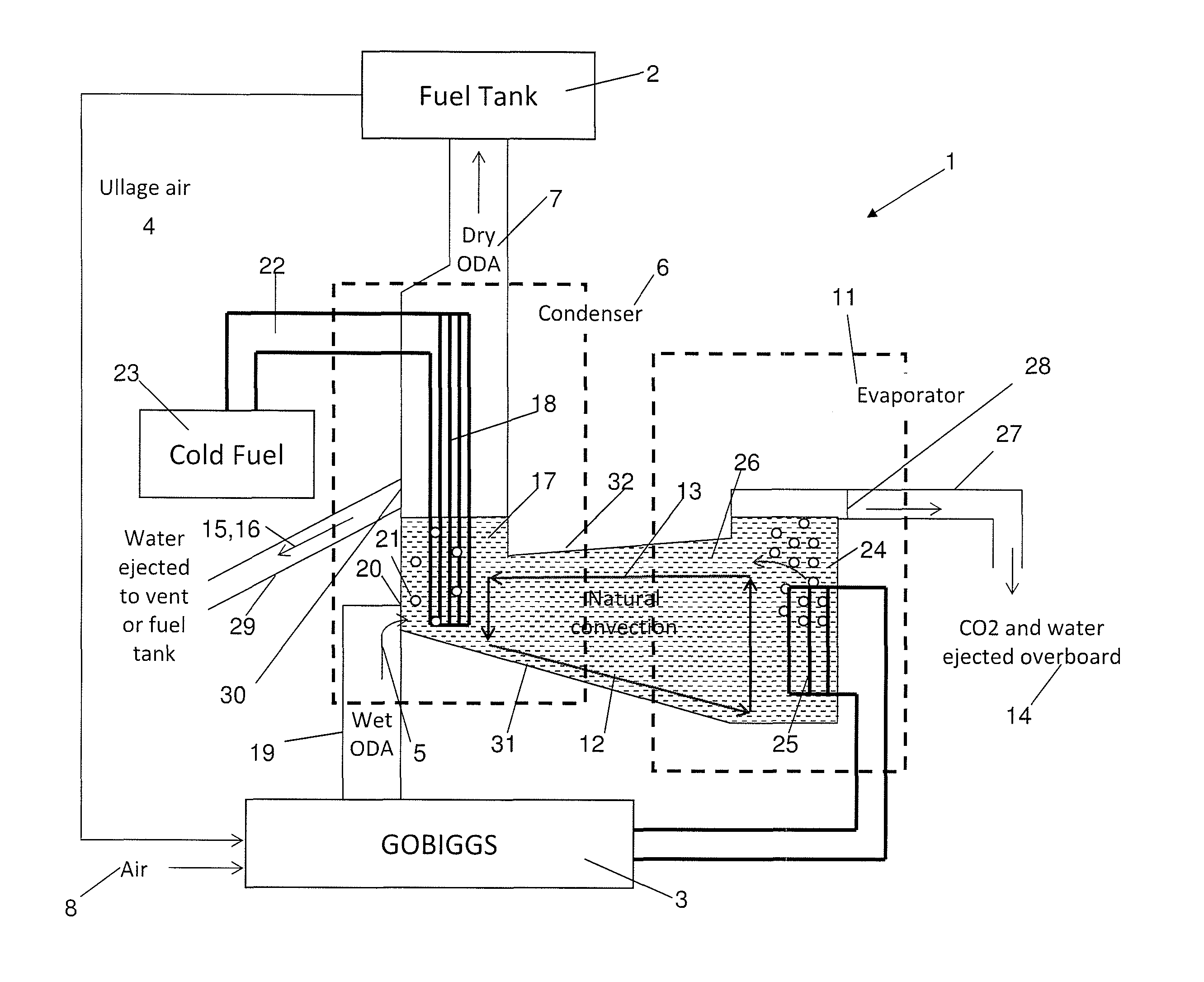
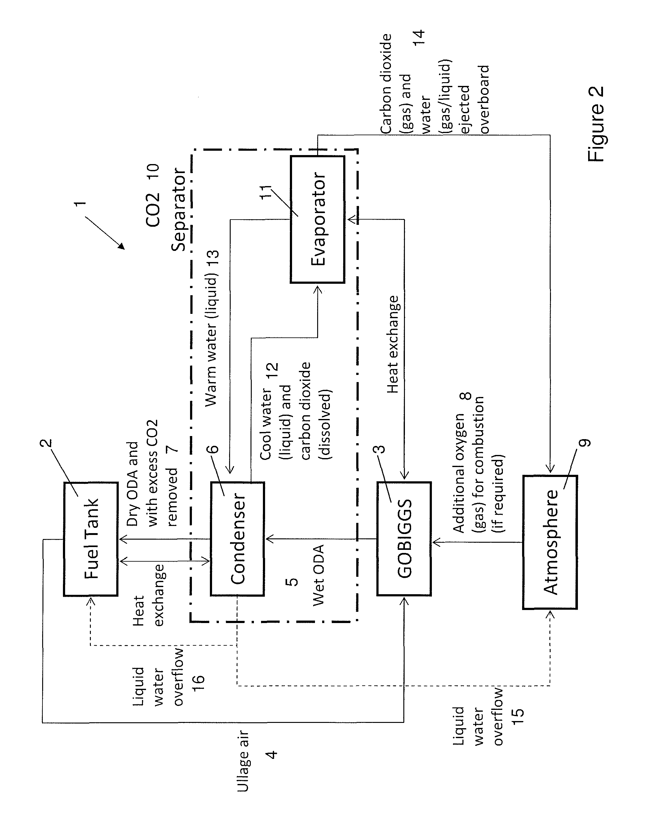
[0037]FIG. 2 illustrates a block diagram of a fuel system 1 for inerting and dehydrating a fuel tank such as, for example, the aircraft wing fuel tank architecture 100 shown in FIG. 1. The fuel system 1 may alternatively be used with a variety of different v...


PUM

PropertyMeasurementUnit
temperaturesaaaaaaaaaa
heat of combustionaaaaaaaaaa

Abstract

A fuel system comprising a fuel tank, a catalytic inerting device for producing oxygen depleted air (ODA) by reaction of fuel vapor from the fuel tank with air, and a separator device for separating carbon dioxide from the ODA gas before feeding the carbon dioxide depleted ODA gas to the fuel tank so as to render the fuel tank ullage atmosphere inert. Also, a method of reducing the carbon dioxide content of oxygen depleted air (ODA) produced by a catalytic inerting device for inerting a fuel tank ullage atmosphere, the method comprising separating carbon dioxide from the ODA gas before feeding the carbon dioxide depleted ODA gas to the fuel tank. The system may be installed in an aircraft.

Description

RELATED APPLICATIONS[0001]The present application is based on, and claims priority from, British Application Number 1107545.4, filed May 6, 2011, the disclosure of which is hereby incorporated by reference herein in its entirety.FIELD OF THE INVENTION[0002]The present invention relates to a fuel system with an inerting device for rendering a fuel tank ullage atmosphere inert, and a corresponding method.BACKGROUND OF THE INVENTION[0003]Fuel tanks for storing liquid fuel are used, for example, for transporting or storing fuel and on vehicles for their propulsion systems. The volume of gas above the liquid fuel within the fuel tank is known as the ullage. The ullage can contain reactive components, such as oxygen and / or fuel vapours, which can be a potential fire / explosion hazard. The term “inerting” refers to the process of depleting one or more of these reactive components to reduce this potential hazard.[0004]Various inerting systems are known in the art. For example, the potentiall...

Claims


Application Information

Patent Timeline
Patent Type & Authority Patents(United States)
IPC IPC(8): B01D53/46
CPCB64D37/32Y02C10/06Y02T50/44Y02C20/40Y02T50/40
Inventor K-WLAM, JOSEPHHYLANDS, GREGORY
Owner AIRBUS OPERATIONS LTD
Why Eureka
Try Eureka