
Method of depositing material

a material and depositing technology, applied in the direction of crystal growth process, polycrystalline material growth, chemically reactive gas, etc., can solve the problems of low deposition rate and carbon contamination of the deposit, increase the resistivity of the deposit, and undesirable high resistivity, so as to improve the deposition process

Active Publication Date: 2014-10-07
FEI CO
View PDF20 Cites 10 Cited by
  • Summary
  • Abstract
  • Description
  • Claims
  • Application Information

AI Technical Summary

Benefits of technology

This approach enables rapid deposition of high purity materials at a microscopic or nanoscopic scale, independent of beam current, with the ability to control deposition rates and resistivity, overcoming the limitations of prior art by maintaining purity and increasing deposition efficiency.

Problems solved by technology

Two disadvantages of charged particle beam-induced deposition are low deposition rates and carbon contamination of the deposit.
Carbon from the precursors, or from other sources such as lubricants in the vacuum chamber, typically contaminates the deposited metallic material, greatly increasing the resistivity of the deposit.
The slow deposition rate and the high resistivity are undesirable for nanoprototyping and nanoresearch applications.
Various techniques have been tried to improve the purity of beam-induced deposits, but have met with limited success.
Pure deposits have been achieved in electron beam-induced deposition in ultra high vacuum systems, but such systems significantly increase cost and the deposit rate is still low.
Use of an oxidizer is often undesirable because it results in oxide formation or incomplete reduction of the precursor gas.

Method used


Image

  • Method of depositing material
  • Method of depositing material
  • Method of depositing material

Examples


Embodiment Construction

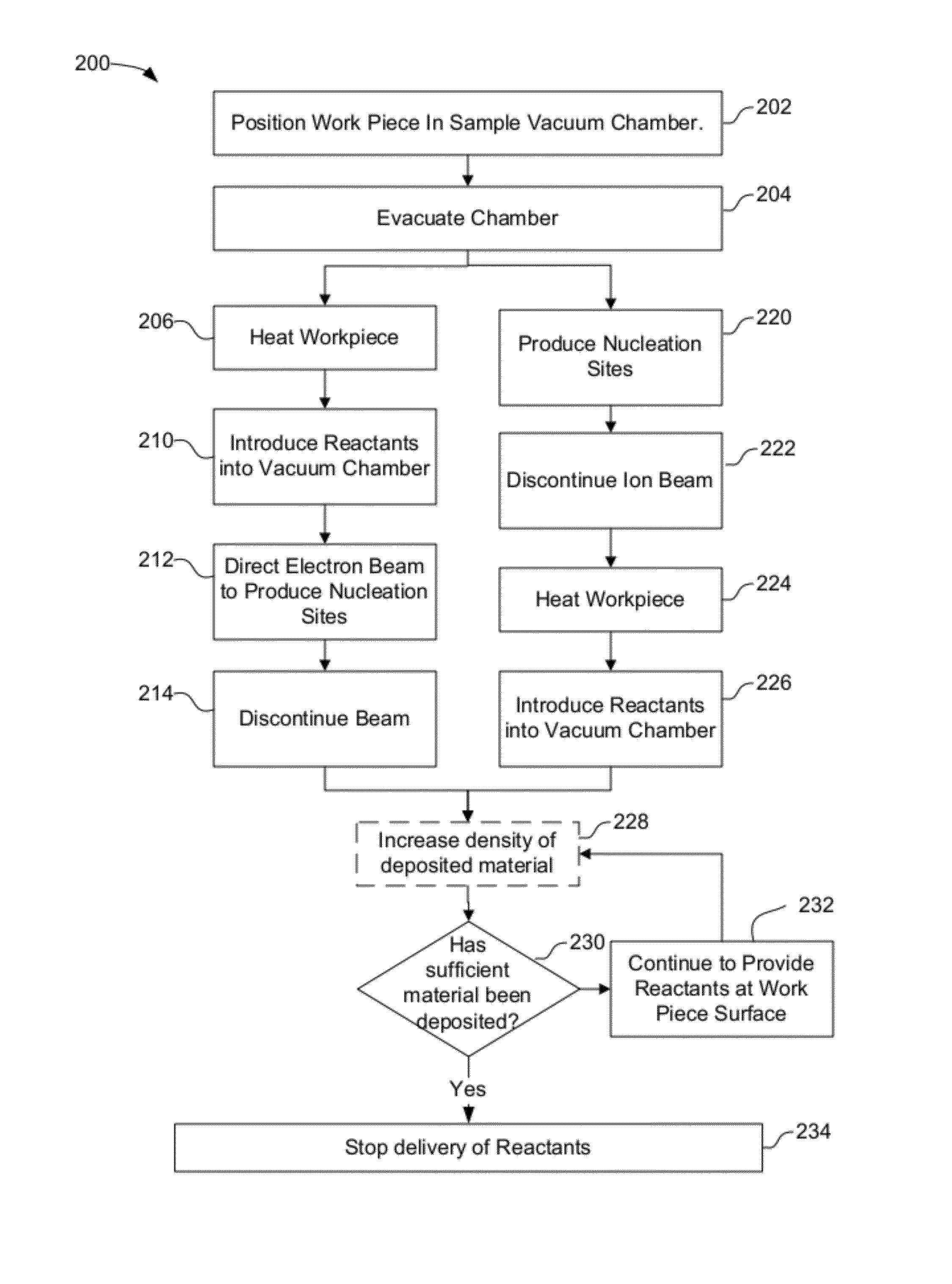
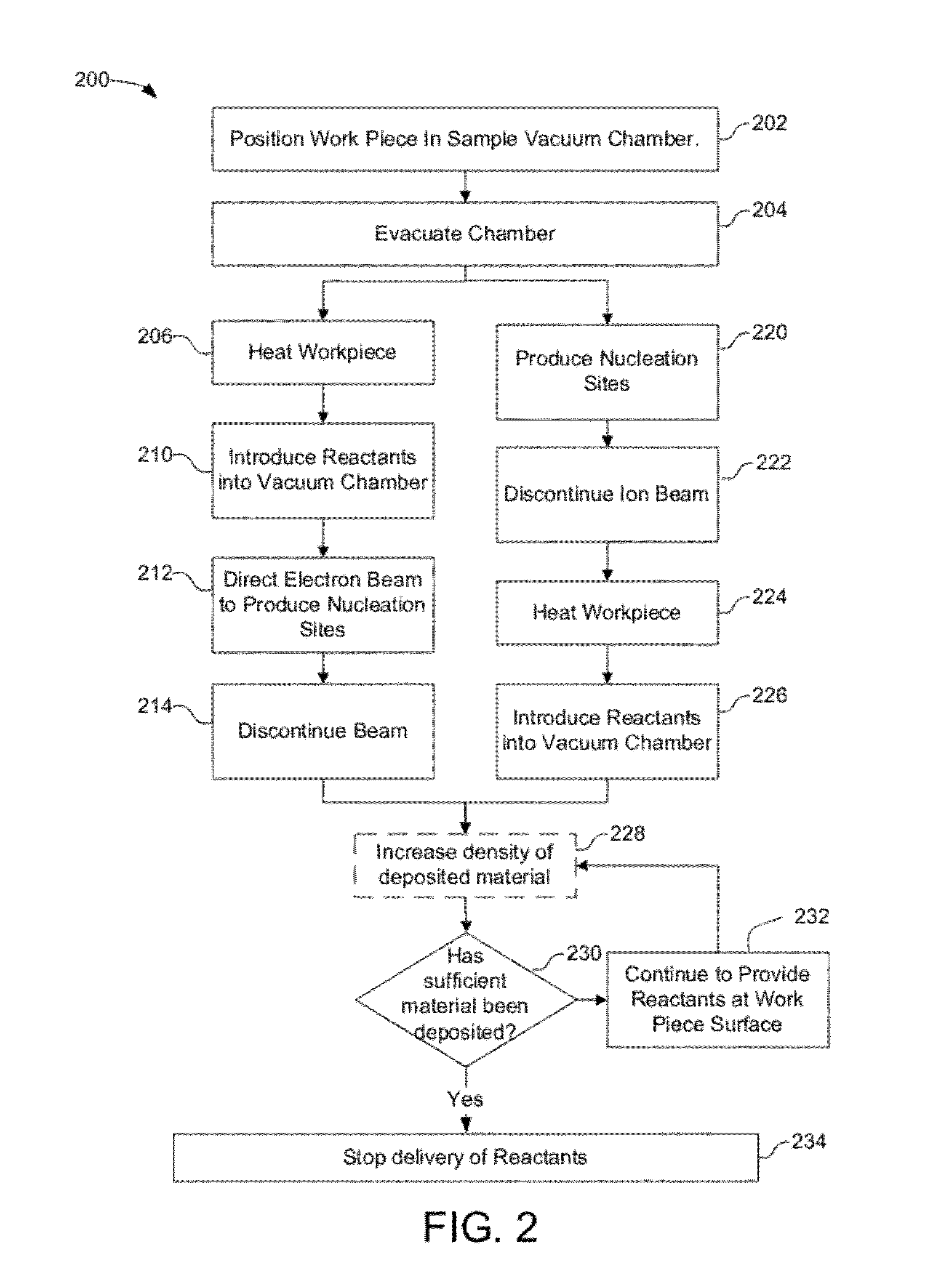
[0022]In accordance with a preferred embodiment of the present invention, a spontaneous decomposition reaction involving two or more species results in rapid deposition of a high purity material. Some embodiments mix two chemicals, a precursor and an activator, that react spontaneously and would therefore have been considered incompatible in the prior art. In some embodiments, the reactants react spontaneously to fully decompose a metal-containing reactant to deposit an essentially pure metal onto the substrate, sample or work piece. In other embodiments, the reaction causes etching of the substrate, sample or work piece.

[0023]Embodiments of the invention deposit material in a pattern by providing local conditions in the desired pattern to enable the spontaneous decomposition reaction, while maintaining conditions that inhibit the reaction on the rest of the work piece surface. The reaction may be inhibited globally, for example, by decreasing the surface residence time of the speci...


PUM

PropertyMeasurementUnit
temperatureaaaaaaaaaa
angleaaaaaaaaaa

Abstract

Material is deposited in a desired pattern by spontaneous deposition of precursor gas at regions of a surface that are prepared using a beam to provide conditions to support the initiation of the spontaneous reaction. Once the reaction is initiated, it continues in the absence of the beam at the regions of the surface at which the reaction was initiated.

Description

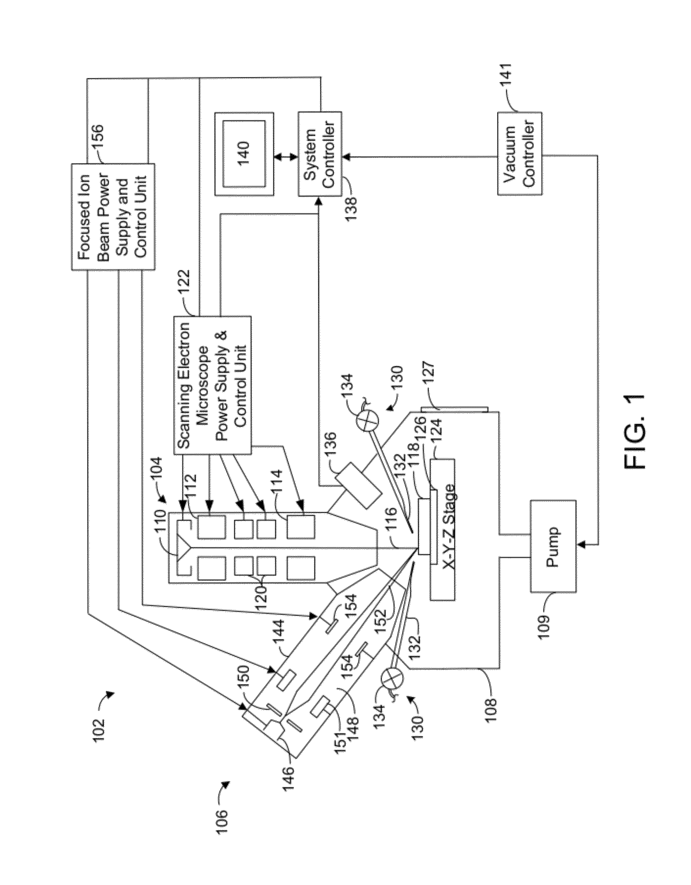
TECHNICAL FIELD OF THE INVENTION[0001]The present invention relates to a method and apparatus for depositing material in a pattern that includes features on a microscopic or nanoscopic scale.BACKGROUND OF THE INVENTION[0002]Beam systems, such as electron beam systems, ion beam systems, laser beam systems, cluster beam systems, and neutral particle beam systems, are used to create features on a surface by etching or depositing material. Beam-induced deposition processes typically use a precursor gas that reacts in the presence of the beam to deposit material on the surface in areas where the beam impacts. For example, a gaseous organometallic compound, such as tungsten hexacarbonyl, is provided near the sample and is adsorbed onto the surface. The organometallic compound decomposes in the presence of a beam, such as an ion beam or an electron beam, to form a metal that remains on the surface and a volatile organic compound that is removed by a vacuum pump. Because the precursor is st...

Claims


Application Information

Patent Timeline
Patent Type & Authority Patents(United States)
IPC IPC(8): H01L21/44C23C16/10C23C16/14C23C16/48
CPCC23C16/48C23C16/10C23C16/14C23C16/0263C23C16/52C23C16/4488C23C16/486
Inventor BOTMAN, AURELIEN PHILIPPE JEAN MACLOURANDOLPH, STEVENTOTH, MILOS
Owner FEI CO
Learn More