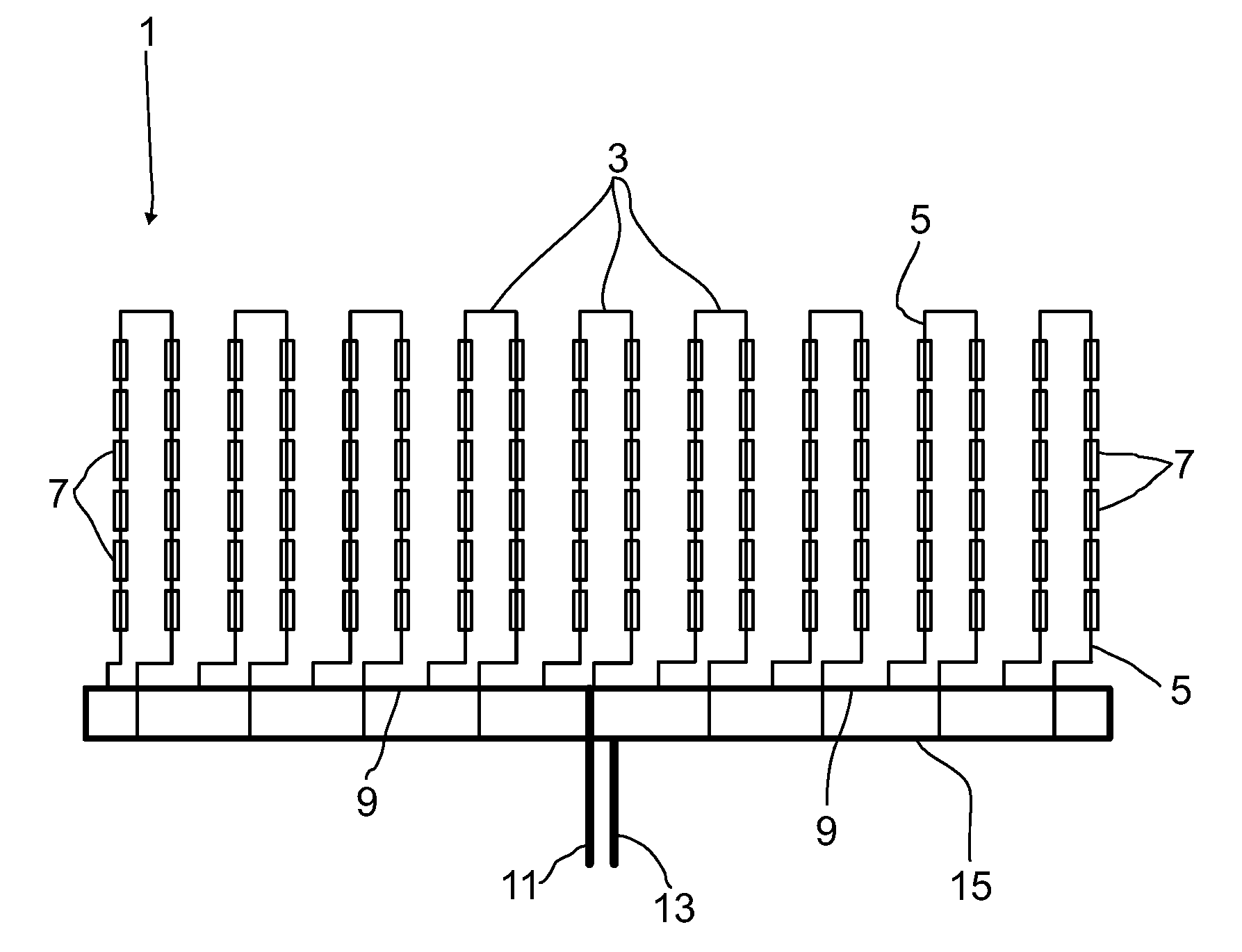
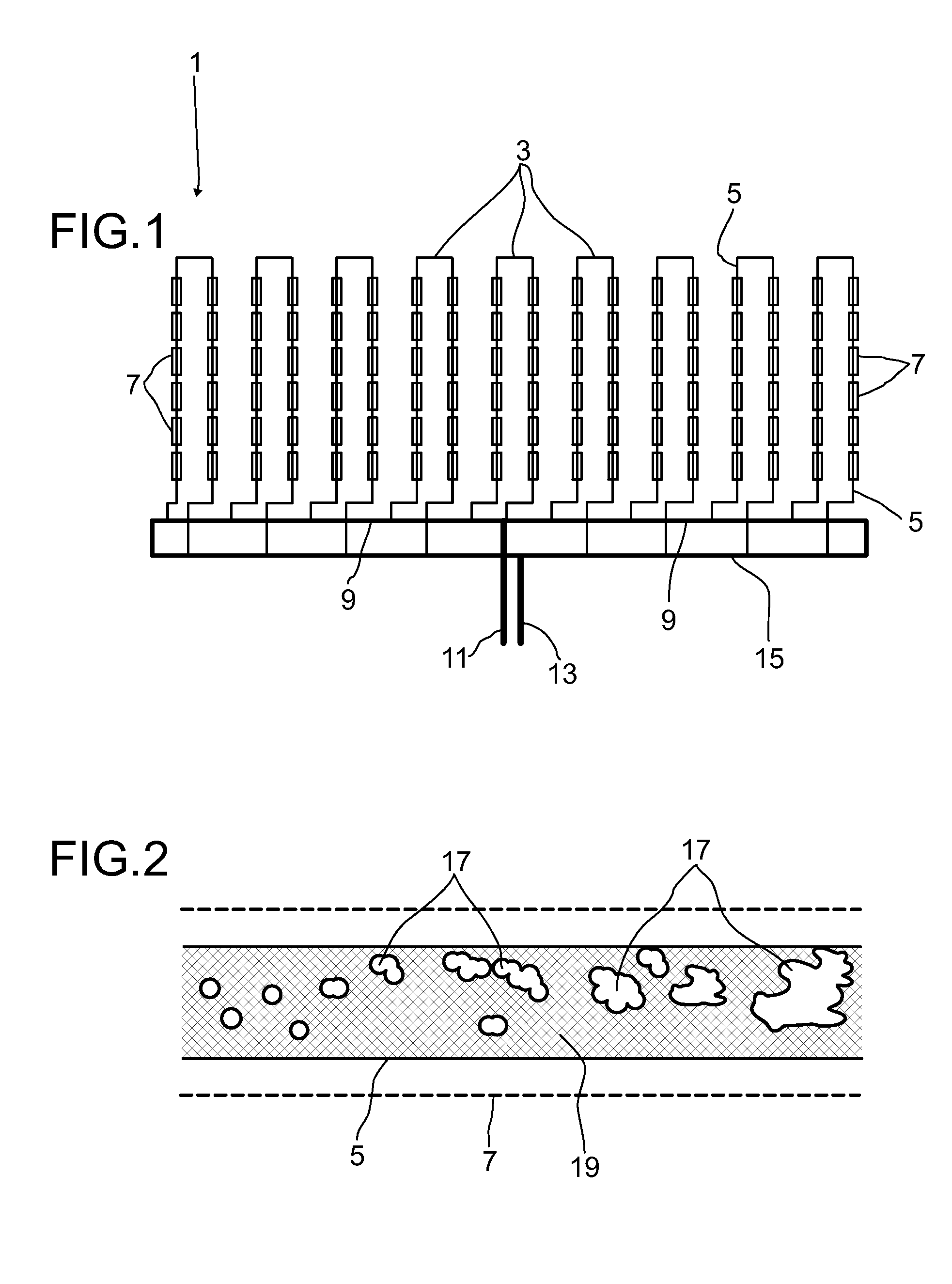
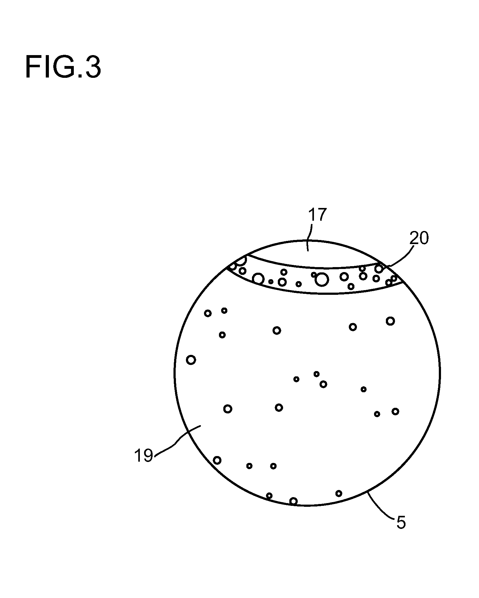
Pipeline for carrying a molten salt

a technology of molten salt and pipeline, which is applied in the safety of solar heat collectors, lighting and heating apparatus, furnaces, etc., can solve the problems of high melting point, difficult to reliably operate with molten salts with high melting points, and large commercial losses, so as to reduce the operating temperature of the heat transfer salt and reduce the heat dissipation of the solar array

Active Publication Date: 2014-11-25
BASF AG
View PDF14 Cites 6 Cited by
  • Summary
  • Abstract
  • Description
  • Claims
  • Application Information

AI Technical Summary

Benefits of technology

[0019]It is an object of the invention to provide a pipeline for carrying a molten salt that allows heat transfer salt that has solidified in the pipeline to melt again without causing damage to ...

Problems solved by technology

However, a disadvantage of molten salts is that they have a high melting point.
For example, a sodium-potassium nitrate mixture melts in the eutectic system, that is to say in a mixing ratio of 44:56, at a temperature of 218° C. In long pipeline networks, as occur in solar power plants, it is difficult to operate reliably with molten salts that have high melting points.
The freezing of the molten salt in pipeline systems can cause great commercial losses.
The losses are caused, for example, by the great volumetric expansion of molten salts when they melt.
There is the risk of fittings and pipelines being subjected to pressure and greatly damaged.
When remelting occurs, if there happens to be a great spatial distance between the locations where melting occurs with volumetric expansion and the evacuated regions, there may not be sufficient volumetric equalization to reduce the pressures occurring.
These methods have the disadvantage that considerable amounts of energy in the form of electrical energy or in the form of thermal energy have to be consumed for this.
This technique cannot be used, however, in the case of solar receivers such as are used in parabolic-trough solar power plants, since the individual receivers are thermally insulated very well from the surroundings by an evacuated glass casing.
This has the disadvantage, however, that varying transfer...

Method used


Image

  • Pipeline for carrying a molten salt
  • Pipeline for carrying a molten salt
  • Pipeline for carrying a molten salt

Examples


example 1

[0191]A heating conductor 21 configured as a high-grade steel rod is used for heating a 200 m long pipeline. The heating conductor has a diameter of 25 mm. The heating conductor is in this case produced from high-grade steel St 1.4301.

[0192]The resistivity of the heating conductor 21 is 0.00073 Ω / mm at an operating temperature of 290° C. The specific power required for the heating is 100 W / m. The voltage applied for the heating is 77.3 V and the current intensity is 259 A. The power required on account of the length of 200 m is 20 kW. However, this power is only required during the very short melting time.

[0193]If a higher voltage is used for the heating, it is possible to choose a smaller cross section of the heating conductor. The thermal output dropping across the heating conductor may, for example, be reduced by thyristor-switched pulsed operation.

[0194]If the heating conductor is attached in the pipeline 5 by way of heating conductor holders which are not electrically insulated...

example 2

[0197]A pipeline of high-grade steel 1.4541 has a conductivity of 1.7 m / (ohms·mm2) and an inside diameter of 65 mm and a wall thickness of 2 mm. The cross-sectional area of the pipeline is 421 mm2. The conductivity of the pipe is 716 m / ohm. If 90% of the development of heat is intended to take place on an internal conductor inside the pipeline, it is necessary that the internal conductor takes up 10 times the amount of current. For this purpose, it requires a conductivity of 7.157 m / ohm. Copper has at a temperature of 20° C. an electrical conductivity of 56.2 m / (ohms·mm2). This gives a necessary cross-sectional area for an internal conductor of copper of 127 mm2. This corresponds to a copper wire with a diameter of 12.7 mm or three copper wires each with a diameter of 7.4 mm. If an internal conductor of aluminum is to be used, this requires for the same conductivity a diameter of 15.8 mm.

[0198]On account of the very much smaller mass, and consequently the very much smaller heat capa...


PUM


Abstract

The invention relates to a pipeline for carrying a molten salt, with a pipe wall that is stable with respect to the temperatures occurring. A heating conductor (21) is provided inside the pipeline (5) for heating, the heating conductor (21) preferably not lying against the inner wall of the pipeline (5).

Description

CROSS-REFERENCE TO RELATED APPLICATIONSPriority[0001]Priority is claimed to U.S. Provisional Patent Application Ser. No. 61 / 487,719, filed May 19, 2011, and to U.S. Provisional Patent Application Ser. No. 61 / 539,494, filed Sep. 27, 2011. The disclosures of the aforementioned priority applications are incorporated herein by reference in their entirety.STATEMENT REGARDING FEDERALLY SPONSORED RESEARCH OR DEVELOPMENT[0002]Not ApplicableTHE NAMES OF THE PARTIES TO A JOINT RESEARCH AGREEMENT[0003]Not ApplicableINCORPORATION-BY-REFERENCE OF MATERIAL SUBMITTED ON A COMPACT DISC OR AS A TEXT FILE VIA THE OFFICE ELECTRONIC FILING SYSTEM (EFS-WEB)[0004]Not ApplicableSTATEMENT REGARDING PRIOR DISCLOSURES BY THE INVENTOR OR A JOINT INVENTOR[0005]Not ApplicableBACKGROUND OF THE INVENTION[0006]1. Field of the Invention[0007]The invention is based on a pipeline for carrying a molten salt, with a pipe wall that is stable with respect to the temperatures occurring.[0008]2. Description of Related Art[...

Claims


Application Information

Patent Timeline
IPC IPC(8): F24J2/46E03B7/10F27D11/00
CPCF24J2/4649F27D11/00F24J2/4632F24J2/4607F03G6/067Y02E10/40Y02E10/46F24S40/00F24S40/70F24S80/20
Inventor WORTMANN, JURGENLUTZ, MICHAELGARTNER, MARTINSCHIERLE-ARNDT, KERSTINMAURER, STEPHANLADENBERGER, MICHAELGEYER, KAROLINGARLICHS, FLORIAN
Owner BASF AG
Why Eureka
Try Eureka