Method and apparatus for control of electrochromic devices

a technology of electrochromic devices and control methods, applied in the direction of instruments, spectacles/goggles, optics, etc., can solve the problems of device degradation, damage and cessation of device function, and irreversible oxidative or reductive degradation, so as to increase the switching speed and reduce the electrochromic switching time

Active Publication Date: 2014-12-02
ASHWIN USHAS
View PDF81 Cites 106 Cited by
  • Summary
  • Abstract
  • Description
  • Claims
  • Application Information

AI Technical Summary

Benefits of technology

[0012]Accordingly, the invention provides devices and methods that overcome the obstacles present in the field. Specifically, the invention provides pulsed, continuous voltage methodology that applies voltages greatly exceeding that corresponding to the redox stability limits of the subject electrochromic system. However, these voltages are applied for very short periods of time, for example, in the range of several hundred milliseconds (ms) or less. Therefore, the methods and devices of the invention provide greatly increased switching speed (i.e. reduce the electrochromic switching time), by a factor of 10 or more without degrading the electrochromic system.

Problems solved by technology

When the maximum applied voltage is exceeded (in which case an “overvoltage” or “overpotential” is said to be applied), irreversible oxidative or reductive degradation may occur, with consequent damage and cessation of function of the device.
However, the trade off is degradation of the device.

Method used


Image

  • Method and apparatus for control of electrochromic devices
  • Method and apparatus for control of electrochromic devices
  • Method and apparatus for control of electrochromic devices

Examples


example 1

[0081]An electrochromic device was prepared utilizing a cathodically coloring conducting polymer that includes the monomer 2,2-bis(4-chlorobenzyl)-3,4-propylenedioxythiophene and an anodically coloring conducting polymer that includes the monomer N,N′-diphenyl benzidine. Regarding the properties of the electrochromic device described above, the typical transmission (% T) spectrum, in the UV-Vis-NIR region, of such device is disclosed in FIG. 4.

[0082]Additionally, a cyclic voltammogram (CV) of the electrochromic system is disclosed in FIG. 5, taken at a very slow scan rate (10 mV / s); this CV is of an exemplary electrochromic lens in 2-electrode mode, i.e. with no reference electrode. The highly reversible nature of the redox behavior for this system is demonstrated herein. Indeed, the primary and secondary voltammetric peaks responsible for the electrochromism, [primary at about +250 mV (oxidation, (−) current) about +200 mV (reduction, (+) current), secondary at about −850 mV (oxida...

example 2

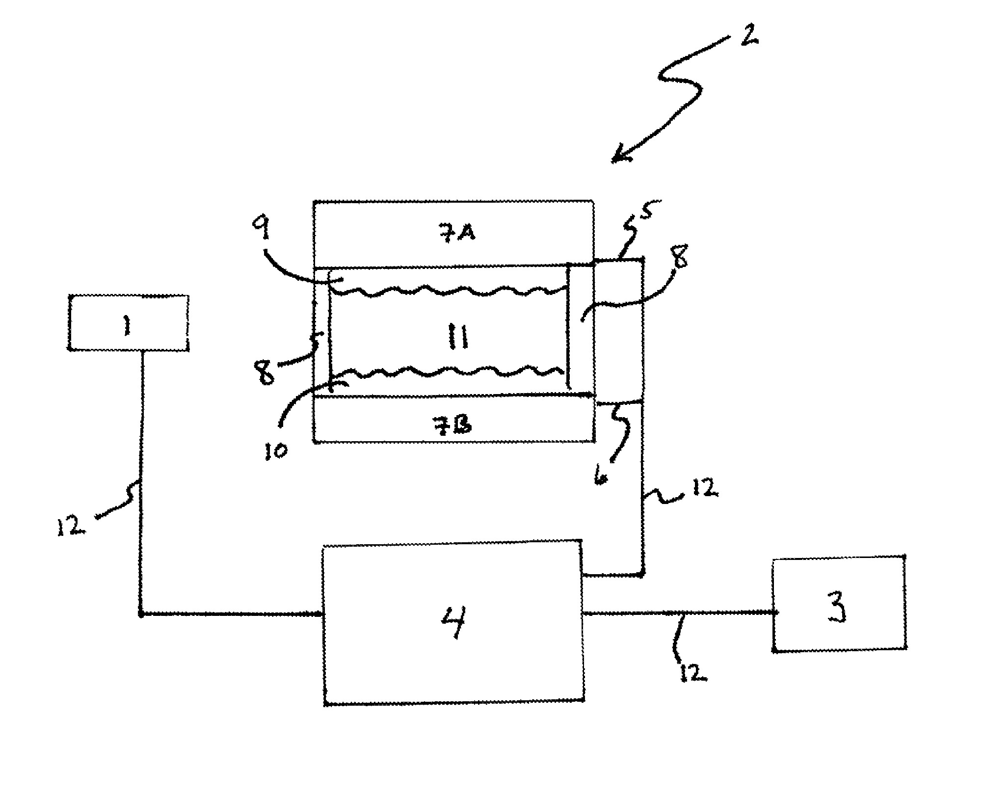
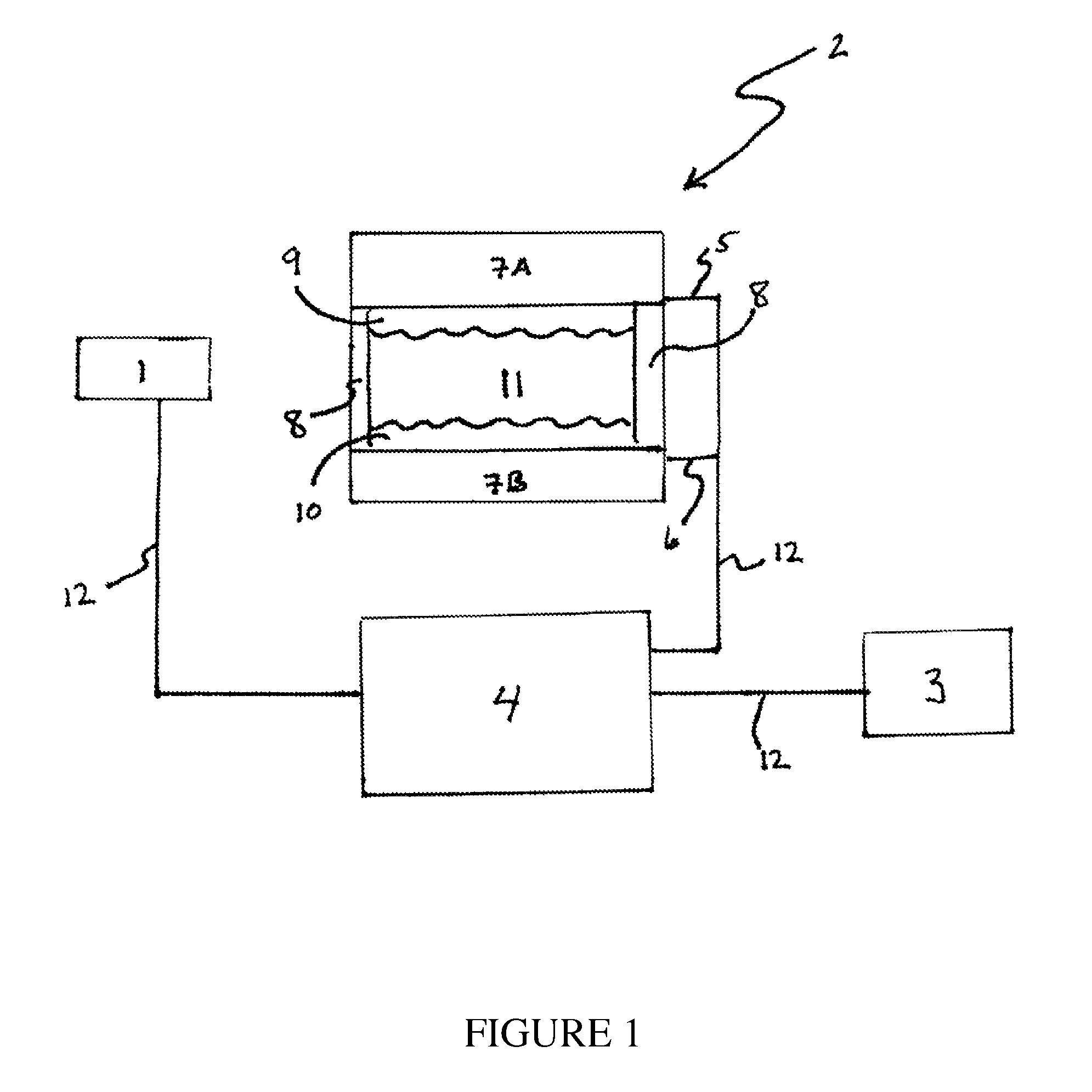
[0085]In practice of the present invention, the photosensor readings, which may be in mV corresponding to particular light levels, may be used as key inputs by the programs of the invention in determining how to drive the electrochromic device, i.e., what voltages to apply and for what duration. For this purpose, the programs of the invention may be associated with a lookup table that may be held in the controller 4 or, more specifically, the microcontroller. A representative look up table is provided herein as Table 1.

[0086]At a reference light level, the reference voltage may be calibrated to 2.5 V; the calibration factor is saved to an EEPROM inside the microcontroller. During normal operation, the photocell voltage (Vpc) is calibrated with the saved calibration factor. The device voltage (Vdev) is adjusted based on the programs of the invention including A, B, C, and D. Vdev is adjusted in steps of 0.25V. (see, for example, FIG. 7).

[0087]

TABLE 1A Representative Look-Up TableVpc ...

example 3

[0088]Demonstrating the differences between the application of the programs of the invention in comparison to the use of a potentiostat, an examination of switching times may be observed (FIG. 8). Indeed, FIG. 8 demonstrates a comparison of the switching time using a steady DC voltage, as applied from potentiostat (or a DC power source), and that obtained using programs A and C (used as examples). The switching time is reduced, from approximately 8 s for the potentiostatic DC voltage to less than 1 s for program C. As set forth above, the switching time is defined customarily as the time for transition between 10% and 90% of the maximum and minimum % T, and the above values are measured using this definition. Additionally, FIG. 9 demonstrates the long term cyclability, at 0 and 10,000 cycles between light and dark states, using program C. There is almost no effect on the electrochromic switching characteristics and stability of the system, even though an overvoltage of ±3.0 V has be...


PUM

PropertyMeasurementUnit
applied voltageaaaaaaaaaa
molar ratioaaaaaaaaaa

Abstract

The present invention provides apparatuses and methods for modulating the transmissivity of electrochromic devices utilizing a controller that provides a continuous potential that may be pulsed to the electrochromic device.

Description

FIELD OF THE INVENTION[0001]The present invention relates generally to devices and methods for modulating electrochromic devices and more particularly but not exclusively to devices and methods for controlling the transmissivity of electrochromic devices by delivering a continuous voltage that is pulsed, which allows for rapid switching between transmissive and non-transmissive states of such electrochromic devices.BACKGROUND OF THE INVENTION[0002]Certain electrochromic materials may change color when applying a voltage. The color change may be in the visible spectrum, but can also be, for example, in the near infrared (NIR), infrared (IR), or microwave spectral region. The change in color of an electrochromic material is usually due to reduction / oxidation (“redox”) processes within the electrochromic materials. Further, electrochromic devices may be switched between a substantially transmissive state and a substantially non-transmissive state depending upon the applied voltage. Ind...

Claims


Application Information

Patent Timeline
Patent Type & Authority Patents(United States)
IPC IPC(8): G02F1/01G02F1/163
CPCG02F1/163G02F2001/1515G02F2001/1502G02F2201/58G02F1/15165G02C7/101G02F1/13318G02F2001/164
Inventor CHANDRASEKHAR, PRASANNA
Owner ASHWIN USHAS
Why Eureka
Try Eureka