
Biogenic fuel and method of making same

a biogenic fuel and fuel technology, applied in the field of engine fuel, can solve the problems of increasing pollution per mile, affecting the quality of fuel, and being difficult to predi

Active Publication Date: 2014-12-09
SWIFT ENTERPRISES
View PDF58 Cites 2 Cited by
  • Summary
  • Abstract
  • Description
  • Claims
  • Application Information

AI Technical Summary

Benefits of technology

The present invention provides a method for producing mesitylene-isopentane fuel using a biomass-derived acetone. The method involves a gas phase reaction of acetone with a catalyst at a specific temperature, pressure, and space velocity. The resulting reaction products are then separated from other by-products. The separated acetone is then converted to isopentane through a series of reactions. The technical effects of this invention include the ability to produce a high-energy content fuel from a biomass-derived acetone, as well as a more efficient and cost-effective method for producing the fuel.

Problems solved by technology

With the end of cheap oil and the mounting peak of world oil production, it is recognized that petroleum is a non-renewable resource and will eventually be depleted.
Effectively, since ethanol-based fuels have lower energy, pollution is generally increased per mile.
It is a kinetic parameter, therefore difficult to predict.
This translates to aircraft range and to specific fuel consumption.
Aircraft cannot compromise range due to the sensitivity of their missions.
Although discrete chemical compounds have been found to satisfy the motor octane number for 100LL octane aviation gasoline, they fail to meet a number of other technical requirements for aviation gasoline.
These paraffinic fuels are not “drop-in” jet fuel for a number of reasons: first, their density falls below allowable 0.775-0.84 range; and second, they tend to cause fuel leaks through o-ring seals (due to the lack of aromatic components).
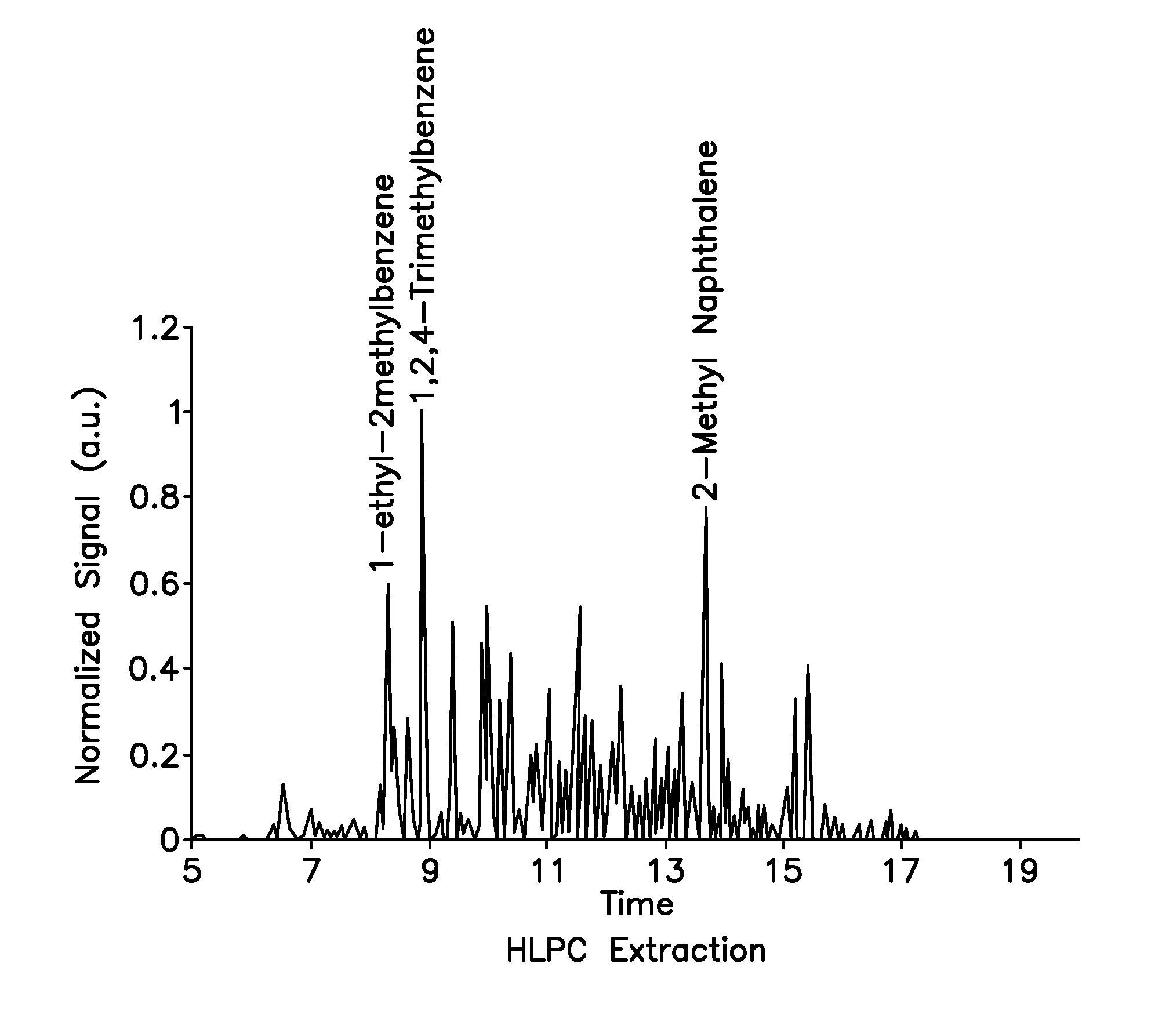
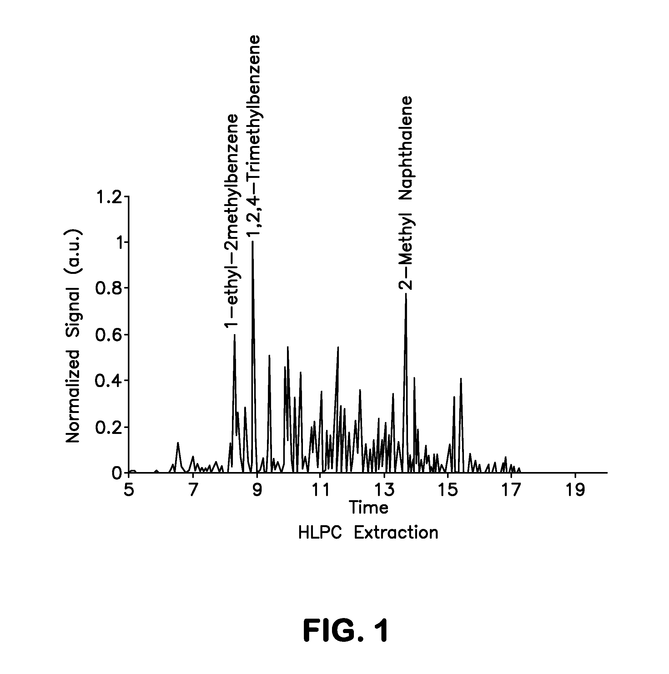
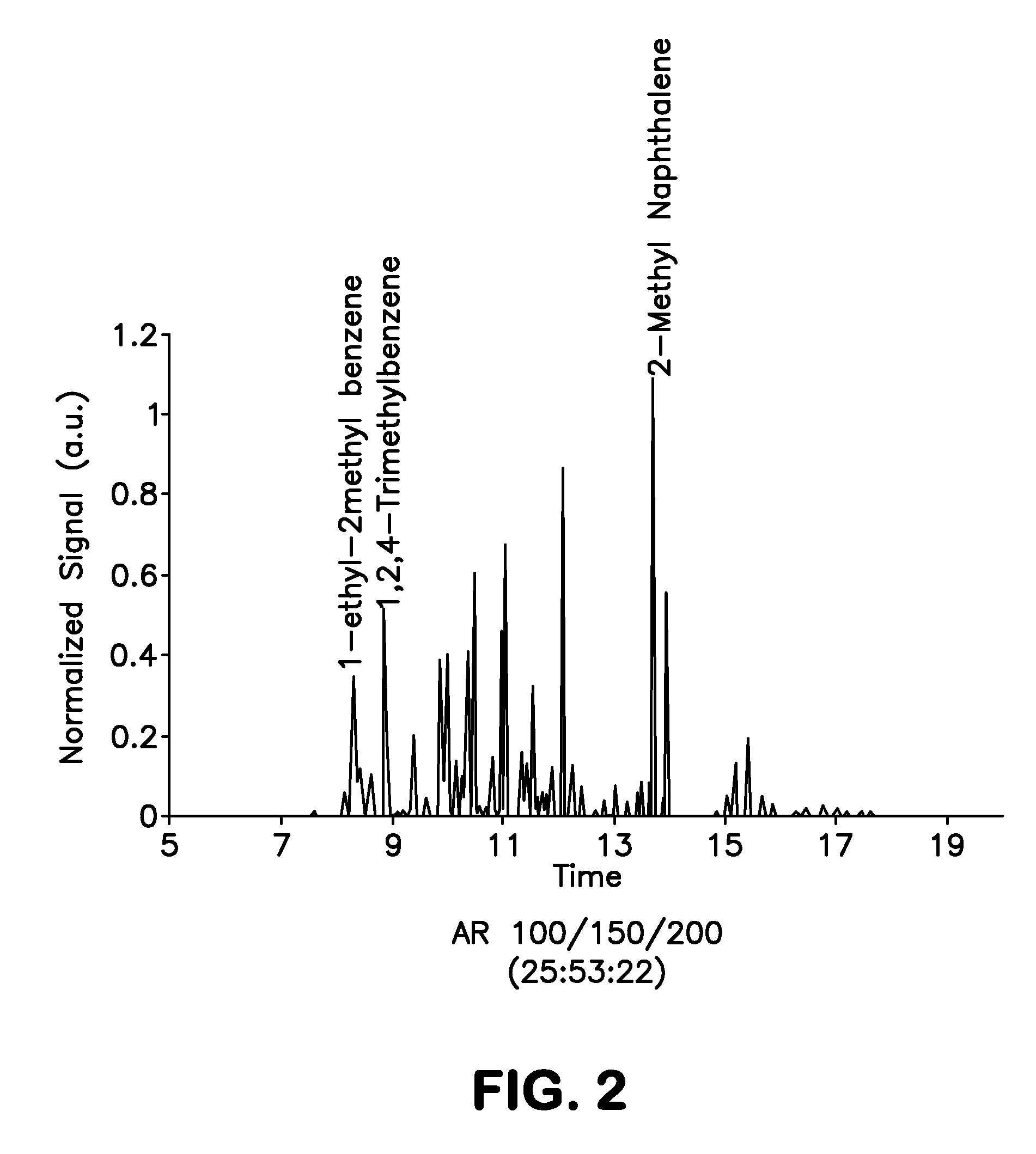
Thus, adding a single-component aromatic component to a fuel (as opposed to a wide-boiling aromatics blend like FIG. 1) might not provide satisfactory properties.
However, this reduction tracks well with the general trend of cetane reduction with aromatic content in jet fuels, so it does not exclude the use of mesitylene blends in diesel engines.
One expected issue with fully-synthetic fuels is lubricity.
Jet fuel lubricity is general thought to come primarily from trace polar impurities in jet fuel, so it might be expected that existing fully-synthetic fuels would have poor lubricity (as indeed they do).
The major issue for addition of synthetic aromatics to fuel blends is the effect of the aromatic addition on the poor lubricity of the base fuel.
Very limited testing with fuel blends without the CI / LI additive were performed, and it was typically seen that mesitylene did not significantly affect the lubricity of the base fuel.
As shown in FIG. 9, the addition of mesitylene to this SPK fuel did, indeed, unexpectedly reduce the smoke point (equivalent to increasing soot emissions), but in a non-linear fashion.
Efforts to verify this behavior led to inconsistent results, so it was decided to compare actual engines emissions in a T63 helicopter engine.
The 16% mesitylene blend also shows significant reductions relative to the JP-8 baseline at both idle and cruise conditions, so it seems clear that addition of mesitylene to alternative fuels does not produce a sooty fuel.
A limited amount of thermal stability testing was performed with mesitylene, with more extensive testing performed with the aromatic blend shown in FIG. 2.
Many aromatics are known to reduce fuel thermal stability although some appear to be relatively benign.
Therefore, addition of petroleum aromatics above some low threshold (below 10%) reduces the thermal stability of SPK and HRJ fuels to typical jet fuel values (where the average aromatic content is 15-20%).
Unfortunately, this method is energy intensive, and accordingly uneconomical.

Method used


Image

  • Biogenic fuel and method of making same
  • Biogenic fuel and method of making same
  • Biogenic fuel and method of making same

Examples


Embodiment Construction

[0101]As discussed above, the present invention provides a non-petroleum-based renewable fuel comprised of fully renewable components, i.e., components derived from bio-sources such as corn. This fuel has several variants, the preferred variants being turbine fuel and diesel fuel. Advantageously, the components of the fuels discussed above are all derivable from plant or animal oils, and the product can be tailored to the input stock. In general, plant oils are preferred due to their lower molecular weight products.

[0102]Both the turbine fuels and the diesel fuels of the present invention provide an overall mix and match with discreet components derivable from all plant or animal oils, and the product can be tailored to the input stock. In general, plant oils are preferred as the base stock for production of the fuel component of the composition, due to their lower molecular weight products. With regards to same, the fuel component can be derived from various plant source bio-oils. ...


PUM

PropertyMeasurementUnit
pressureaaaaaaaaaa
temperatureaaaaaaaaaa
pressureaaaaaaaaaa

Abstract

A method of producing from a biomass mesitylene-isopentane fuel is provided. A biomass may be fermented to form acetone. The acetone is converted in a catalytic reactor to mesitylene and mesityl oxide. The mesitylene is separated in a phase separator and the organic face containing mesityl oxide is sent to a dehydration reactor, then to a demethylation reactor, and finally to a hydrogenation reactor from which isopentane is recovered. This isopentane is then mixed with the mesitylene to form the final mesitylene-isopentane fuel. The catalytic reaction with acetone employs catalysts of either niobium, vanadium or tantalum.

Description

REFERENCE TO RELATED APPLICATIONS[0001]This is a continuation-in-part of U.S. patent application Ser. No. 13 / 028,896, filed Feb. 16, 2011, now U.S. Pat. No. 8,552,232, which is a continuation-in-part of U.S. patent application Ser. No. 12 / 788,010, filed May 26, 2010, now U.S. Pat. No. 8,344,193, which is a continuation-in-part of U.S. patent application Ser. No. 12 / 717,480, filed Mar. 4, 2010, now U.S. Pat. No. 8,556,999, which is a continuation-in-part of U.S. patent application Ser. No. 12 / 139,428, filed Aug. 13, 2008, now U.S. Pat. No. 8,049,048, which is a continuation-in-part of U.S. patent application Ser. No. 11 / 881,565, filed Jul. 27, 2007, now abandoned, which claims priority of provisional U.S. Patent Application Ser. No. 60 / 833,589, filed Jul. 27, 2006, the contents of all of which are incorporated herein by reference.FIELD OF THE INVENTION[0002]The present invention relates in general to an engine fuel produced from renewable materials and, in particular, the present inv...

Claims


Application Information

Patent Timeline
Patent Type & Authority Patents(United States)
IPC IPC(8): C10L1/08C10L1/04C10L1/10B01J23/20C07C5/08B01J37/03C10G3/00C12P7/36C07C4/10C07C5/03C07C7/20C10L1/182C10L1/16C12P7/16C07C1/207B01J21/08C10G45/32C10L1/02
CPCC07C2523/22C10G2300/4012Y02E50/13C12P7/36C10L1/08C10G2400/02C10L1/02C10L1/023Y02E50/10C12P7/16C10G2400/08C10G3/44B01J37/03C07C5/03C10G2400/04C07C5/08C10G3/50B01J21/08Y02E50/343C07C1/2074C10L1/04C10G45/32C10G2300/1014Y02T50/678C10L1/1824B01J23/20C10L1/1608C10G2300/4006C10G2300/4018C10G2300/1018C07C4/10C07C2523/20C12P2203/00Y02P30/20C07C15/02C07C11/21C07C11/28C07C11/22C07C9/18Y02E50/30
Inventor RUSEK, JOHN, J.
Owner SWIFT ENTERPRISES
Learn More