

Developing roller, electrophotographic process cartridge, and electrophotographic image forming apparatus
a technology of electrophotographic image and development roller, which is applied in the direction of electrographic process, application, instruments, etc., can solve the problems of reducing the adhesiveness between the surface layer and the silicone rubber elastic layer, and the developer's charge quantity is responsible for the occurrence, and achieve excellent charge-providing performance
- Summary
- Abstract
- Description
- Claims
- Application Information
AI Technical Summary
Benefits of technology
Problems solved by technology
Method used
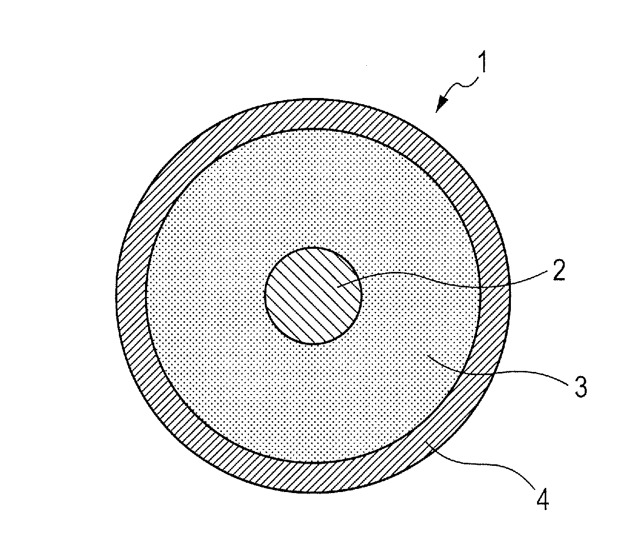
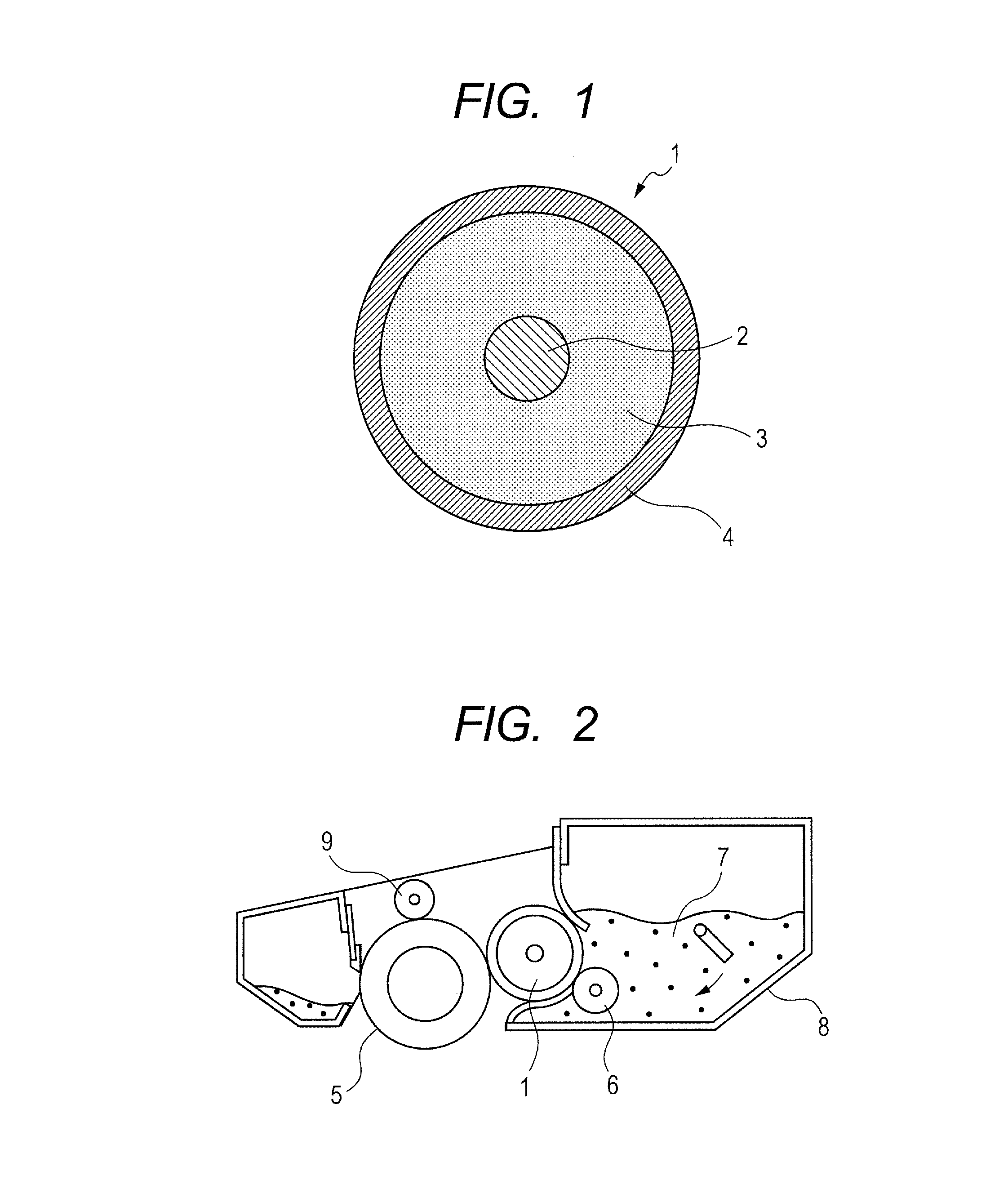
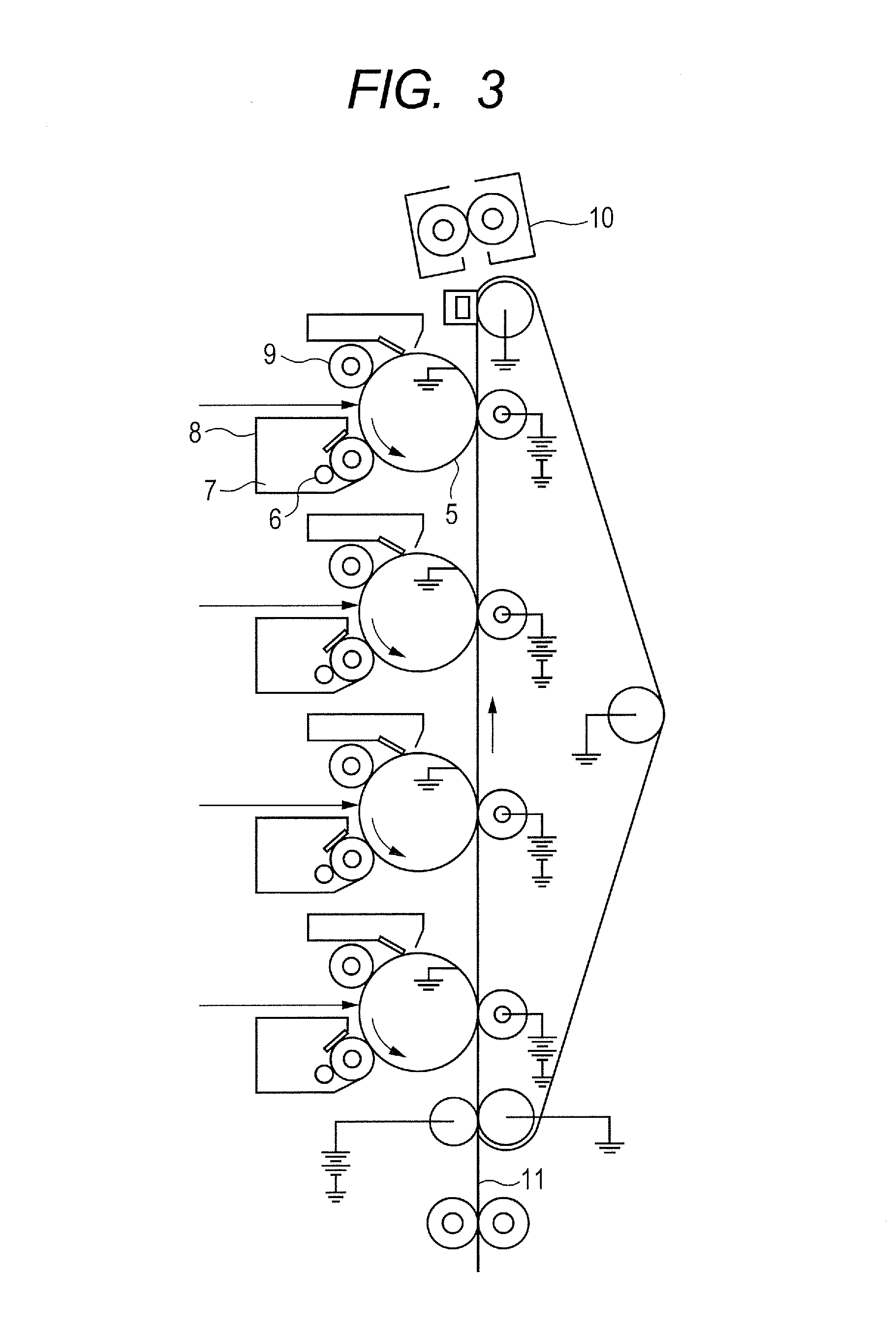
Image

Examples
production example 1
[0075]The following materials were mixed in a four-necked separable flask provided with a stirring machine, a condenser, a temperature gauge, and a nitrogen-introducing tube, and were then stirred until the system became uniform.
[0076]
TABLE 1MaterialCompound namePart(s) by massCopolymerizableDimethylaminoethyl hexadecyl48.5componentacrylate bromide saltDimethylaminoethyl methacrylate5Methyl methacrylate6SolventIsopropyl alcohol100Polymerization2,2′-Azobisisobutyronitrile0.6initiator(hereinafter represented as “AIBN”)
[0077]While the stirring was continued, the temperature in the reaction system was increased to 70° C., followed by a reaction in a reflux state for 8 hours while nitrogen was introduced into the flask. Further, the solution was diluted with ethanol. Thus, a copolymer solution A1 having a solid content of 40 mass % was obtained. The resultant copolymer solution was subjected to the measurement of the weight-average molecular weight of its copolymer by the following molec...
production examples 2 to 20
[0087]Copolymer solutions A2 to A18, and copolymer solutions B1 and B2 were obtained in the same manner as in Production Example 1 except that the copolymerizable components and their blending amounts were changed to conditions shown in Table 2.
[0088]In addition, Table 3 shows the structures of copolymers in the copolymer solutions A1 to A18, and the copolymer solutions B1 and B2 obtained by the foregoing procedure.
[0089]
TABLE 2Co-polymerBlendingBlendingCopoly-BlendingProductionsolutionamountCopolymerizableamountmerizableamountExampleNo.Copolymerizable component 1(g)component 2(g)component 3(g)1A1Dimethylhexadecylaminoethyl acrylate bromide48.5Dimethylaminoethyl5.0Methyl6.02A255.4acrylate2.9methacrylate6.03A353.93.36.04A432.310.06.05A521.613.36.06A6Dimethyltetradecylaminoethyl acrylate bromide45.65.06.07A7Dimethyloctadecylaminoethyl acrylate bromide51.45.06.08A8Dimethyldecylaminoethyl methacrylate bromide41.1Dimethylaminoethyl5.56.09A9Dimethyldodecylaminoethyl methacrylate bromide44...
example 1
[0091]1.
[0092]A product obtained by applying and baking a primer (trade name: DY35-051; manufactured by Dow Corning Toray Co., Ltd.) to a cored bar made of SUS304 having a diameter of 6 mm was prepared as a mandrel.
[0093]2.
[0094]Next, the mandrel was placed in a die and then an addition-type silicone rubber composition obtained by mixing materials shown in Table 4 below was injected into a cavity in the die.
[0095]
TABLE 4MaterialPart(s) by massLiquid silicone rubber material (trade name: SE6724A / B;100manufactured by Dow Corning Toray Co., Ltd.)Carbon black (trade name: TOKABLACK #7360SB;35manufactured by TOKAI CARBON CO., LTD.)Silica powder0.2Platinum catalyst0.1
[0096]Subsequently, the die was heated to subject the silicone rubber to vulcanization curing at 150° C. for 15 minutes, followed by removal the resultant from the die. After that, heating was performed at 180° C. for an additional one hour to complete the curing reaction. Thus, an elastic layer having a thickness of 3 mm w...
PUM
| Property | Measurement | Unit |
|---|---|---|
| humidity | aaaaa | aaaaa |
| temperature | aaaaa | aaaaa |
| primary particle diameter | aaaaa | aaaaa |
Abstract
Description
Claims
Application Information