
Oligomerisation process

a technology of oligomerisation process and zeolite, which is applied in the preparation of physical/chemical process catalysts, hydrocarbon oil treatment products, etc., can solve the problems of zeolite oligomerisation catalyst, inadequacies of conventional tubular reactor start-up methods, and more damage to the molecular structur

Inactive Publication Date: 2014-12-30
EXXONMOBIL CHEM PAT INC
View PDF8 Cites 0 Cited by
  • Summary
  • Abstract
  • Description
  • Claims
  • Application Information

AI Technical Summary

Benefits of technology

The process described in the patent reduces the amount of heat generated during the start-up phase of the reactor, which helps to quickly cool down the catalyst bed and minimize reaction and temperature overshoot. This allows the catalyst to become "conditioned" more quickly, meaning it is ready for normal operation, while minimizing any negative effects on productivity. Overall, this process helps to achieve a higher conversion of the feed olefine or olefins to the desired level and maximizes the overall runlength of a newly-loaded reactor.

Problems solved by technology

We have now found that the conventional procedure for starting up a tubular reactor, as it was used on solid phosphoric acid catalyst, leads to problems with zeolite oligomerisation catalysts.
We have found that the conventional start up method for a tubular reactor is not appropriate for a reactor containing fresh zeolite or molecular sieve catalysts.
This uncontrolled overshoot leads to a fast coking up of the most active sites on the catalyst, which thus become unavailable for further participation in the oligomerisation reaction even before stable early run conditions have been established.
The longer the overshoot lasts, the more damage is caused to the molecular sieve catalyst, and the more undesired heavier oligomers are produced.

Method used


Image

  • Oligomerisation process
  • Oligomerisation process
  • Oligomerisation process

Examples


example 1

Comparative

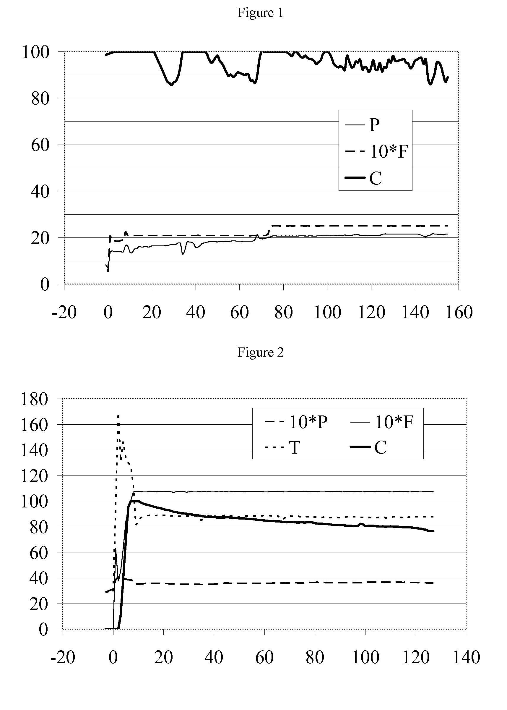
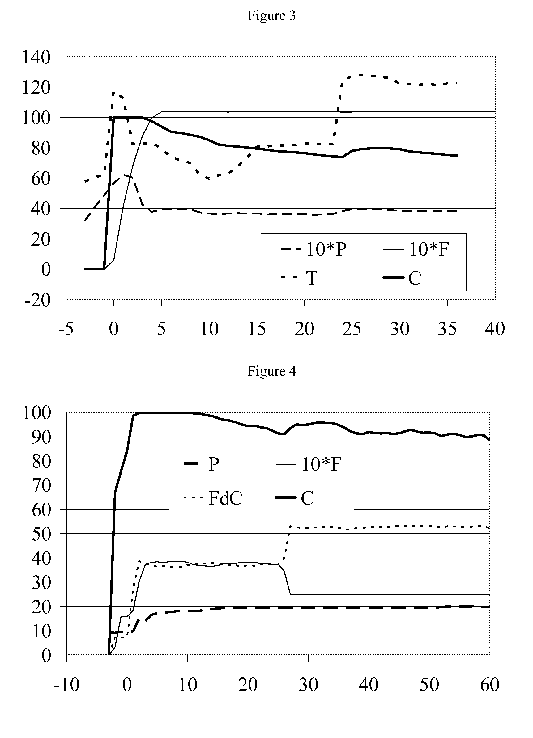
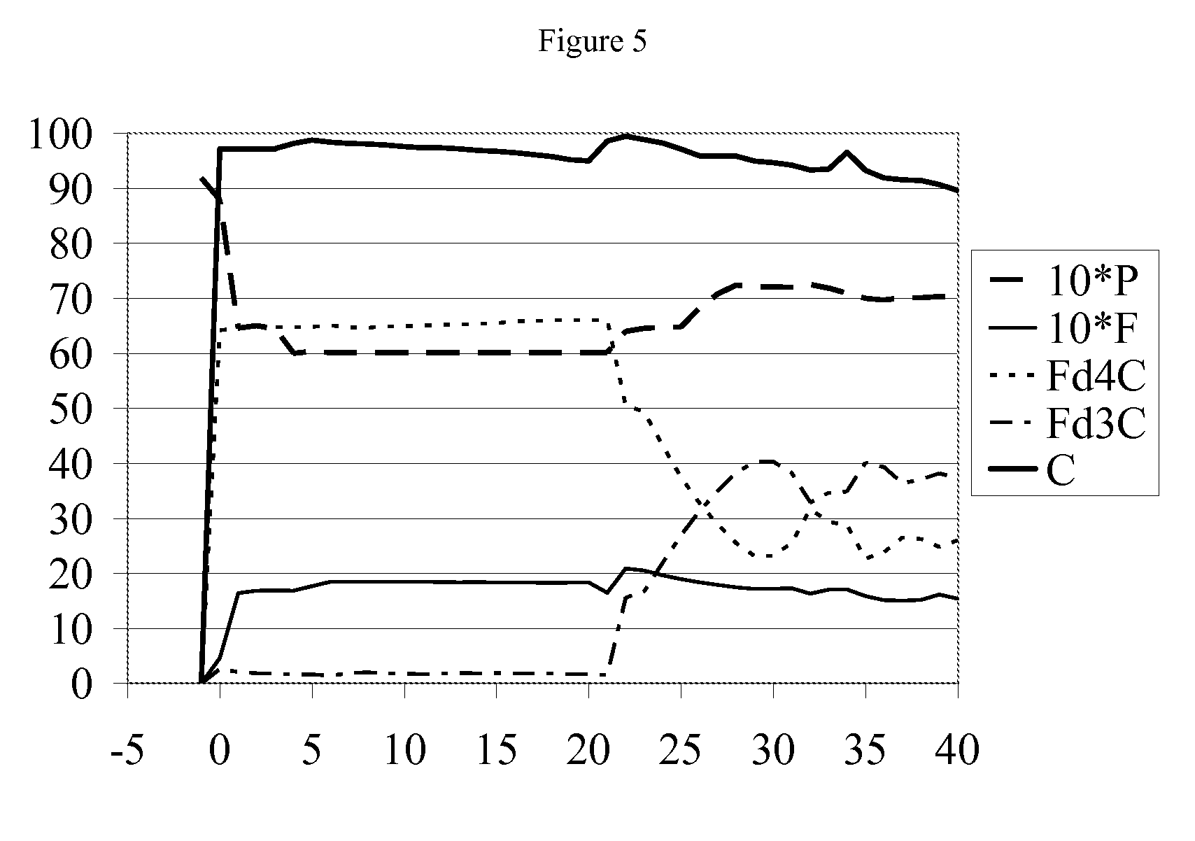
[0074]The tubes of a tubular reactor were loaded with freshly regenerated acidic zeolite catalyst, whereby in the direction of the process flow a first layer of H-ZSM-22 based catalyst preceded a second layer of H-ZSM-57 based catalyst, and whereby the first layer occupied from 40-52% of the volume of the total catalyst bed, on average about 46%. Boiler feed water was introduced into the steam drum connected to the reactor shell side, and into the shell side of the reactor, and a normal liquid level was established in the steam drum. The reactor was preheated to 200° C. by introducing 20 barg saturated steam into the shell side of the reactor. At time 0 hrs, regular olefin feed with the composition given in Table 1 was introduced into the process side of the reactor.

[0075]

TABLE 1Feed (Wt %)TypicalRangeEthane and Ethylene5.705.00-6.40Propane20.4018.90-22.40Propylene52.5850.50-54.80Butane + Isobutane19.1516.50-21.70Trans Butene-20.780.50-1.10Cis Butene-20.660.50-0.80Isobute...

example 2

[0078]The tubes of a tubular reactor were loaded with freshly regenerated acidic zeolite catalyst of the type H-ZSM-57. Boiler feed water was introduced into the steam drum connected to the reactor shell side, and into the shell side of the reactor, and a normal liquid level was established in the steam drum. The reactor was preheated to 135° C. by introducing 40 barg saturated steam into the shell side of the reactor. At time 0 hours, feed with the composition as given in Table 2 was introduced into the process side of the reactor, and which feed was preheated as stated below.

[0079]

TABLE 2Feed (wt %)TypicalRangePropylene0.070.07-0.10Butane47.0543.61-48.61n-Butenes (Butene-1, cis39.2437.64-44.84and trans Butene-2)Isobutane13.4212.31-13.82Isobutene0.150.13-0.18Pentenes0.070.05-0.10Total100.00

[0080]The feed was introduced at a rate equivalent to a weight hourly space velocity (WHSV) in the range of 9-11 (tons / ton / hr or h−1), which is the target for early run conditions on this feedsto...

example 3

[0081]The tubes of a tubular reactor were loaded with freshly regenerated acidic zeolite catalyst, whereby in the direction of the process flow a first layer of H-ZSM-22 based catalyst preceded a second layer of H-ZSM-57 based catalyst, and whereby the first layer occupied from 40-52% of the volume of the total catalyst bed, on average about 46%. Boiler feed water was introduced into the steam drum connected to the reactor shell side, and into the shell side of the reactor, and a normal liquid level was established in the steam drum. The reactor was preheated to 135° C. by introducing saturated 40 barg steam at the shell side of the reactor. At time 0 hours, olefin feed with the composition as given in Table 3 was introduced, and which was preheated to as stated below.

[0082]

TABLE 3Feed (wt %)TypicalRangePropylene0.080.07-0.13Butane42.2341.23-44.23n-Butenes (Butene-1,48.2646.76-50.92cis and trans Butene-2)Isobutane9.159.0-9.5Isobutene0.180.17-0.19Pentenes0.100.08-0.17Total100.00

[0083...


PUM

PropertyMeasurementUnit
temperatureaaaaaaaaaa

Abstract

The startup of a tubular reactor containing fresh or regenerated molecular sieve catalyst and cooled by steam generation on the shell side, as part of an olefin oligomerization process, is improved by, during the startup phase of the reactor, controlling the pressure on the shell side of the reactor at maximum 10 barg. The startup may be further improved by controlling the inlet temperature of the hydrocarbon startup stream to the reactor, by controlling the flow of reactant olefins to the reactor, or by controlling the nature and / or concentration of the olefins in the reactor feed.

Description

PRIORITY CLAIM[0001]This application is a National Stage application of International Application No. PCT / EP2010 / 067989 filed Nov. 23, 2010, which claims the benefit of prior E.P. Patent Application No. 09179262.2 filed Dec. 15, 2009, the disclosures of which are hereby incorporated by reference in their entireties.FIELD OF THE INVENTION[0002]The present invention relates to improvements in or relating to the oligomerisation of olefins over a molecular sieve or zeolite catalyst in tubular reactors. On an industrial scale it is desirable that oligomerisation reactors can run continuously for as long as possible (i.e. achieve long catalyst life) and that the conversion and selectivity of the reaction is maintained over such extended production runs. The present invention is concerned with improving the startup procedure of the tubular reactor in order to contribute to these objectives.BACKGROUND OF THE INVENTION[0003]The condensation reaction of an olefin or a mixture of olefins over ...

Claims


Application Information

Patent Timeline
Patent Type & Authority Patents(United States)
IPC IPC(8): B01J29/90C07C29/04B01J29/40C07C67/303C07C2/12B01J29/70C07C2/04C08F210/16C08F110/06C10G50/00B01J35/00B01J29/80
CPCB01J35/0006C10G2300/1088C10G2300/4031C08F210/08C07C2/12C08F210/16B01J29/90C07C11/02B01J29/7042C08F2500/02C10G2400/20B01J29/7026C10G2400/22B01J29/40B01J29/80C08F110/06C10G50/00Y02P20/584B01J35/19
Inventor HAMILTON, PAULGODSMARK, JOHN S.HEATHER, DAVID E.
Owner EXXONMOBIL CHEM PAT INC
Learn More