Vapor phase growth apparatus and method of fabricating epitaxial wafer

a technology of vapor phase growth and growth apparatus, which is applied in the direction of polycrystalline material growth, crystal growth process, and growth of chemically reactive gases, can solve the problems of raising difficulty in uniformizing the flow route of source, and achieves the reduction of the length of the gas introducing gap, easy adaptation, and minimize the effect of friction resistan

Active Publication Date: 2015-01-06
SHIN-ETSU HANDOTAI CO LTD
View PDF27 Cites 6 Cited by
  • Summary
  • Abstract
  • Description
  • Claims
  • Application Information

AI Technical Summary

Benefits of technology

[0015]The vapor phase growth apparatus of this invention is such as forming a flow passageway of the source gas, flowing up over the susceptor disposed in the reaction vessel, by the bank component (lower liner) and the upper lining component (upper liner). As described in the above, the source gas flowing through the apparatus tends to flow while selecting a position where the frictional resistance can be minimized as possible. The vapor phase growth apparatus of this invention is adjusted so as to decrease the length of the gas introducing gap as distanced from the horizontal standard line in the width-wise direction, or remained constant at any position. The flow of the source gas is, therefore, prevented from largely changing from the direction of the horizontal standard line, where distanced from the horizontal standard line. As a consequence, a vapor phase growth apparatus capable of forming a silicon single crystal film having a desirable thickness distribution can be realized.
[0016]In one preferred embodiment, the above-described vapor phase growth apparatus may be configured so that the degree of overlapping, in the vertical direction, of the top surface of the bank component forming the gas introducing gap and the lower surface of the lining component forming the same is reduced as distanced from the horizontal standard line in the width-wise direction, or remained constant at any position. This configuration allows adjustment of the length-to-be-formed of the gas introducing gap through adjustment of the degree of overlapping between the bank component and the upper lining component, and is therefore readily adaptive to any changes in design and so forth.
[0017]The inner periphery of the lower surface of the upper lining component may be located on the upstream side, in the direction of flow of the source gas, rather than on the inner periphery of the top surface of the bank component. It is necessary for the source gas to flow over the top surface of the bank component, and to be smoothly guided onto the top surface of the susceptor. According to the above-described configuration, the end of the gas introducing gap can be fixed at the position of the inner periphery of the lower surface of the upper lining component, so that the length-to-be-formed of the gas introducing gap can be adjusted while ensuring smooth guidance of the source gas onto the top surface of the susceptor.
[0021]It is also possible to provide the vapor phase growth apparatus with an evacuation system keeping the inner space of the reaction vessel under a reduced pressure lower than the atmospheric pressure. This configuration allows epitaxial growth under a reduced pressure condition contributive to reduction in the degree of pattern deformation, when it is desired to proceed the vapor phase growth on a substrate having patterns already formed thereon.
[0024]It is also preferable to set the degree of opening of an inner valve regulating flow rate of the source gas flowing closer to the horizontal standard line, and an outer valve regulating flow rate of the source gas flowing more distant from the horizontal standard line, corresponding to the length-to-be-formed of the gas introducing gap in the direction in parallel with the horizontal standard line. According to this configuration, any non-conformity in the flow rate of the source gas over the substrate can be reduced, as a result of synergistic effect of the above-described configuration of the vapor phase growth apparatus of this invention.

Problems solved by technology

This is one cause for raising difficulty in uniformalizing the flow route of the source gas flowing over the silicon single crystal substrate.

Method used


Image

  • Vapor phase growth apparatus and method of fabricating epitaxial wafer
  • Vapor phase growth apparatus and method of fabricating epitaxial wafer
  • Vapor phase growth apparatus and method of fabricating epitaxial wafer

Examples


experimental cases

(Computer Simulation Experiments)

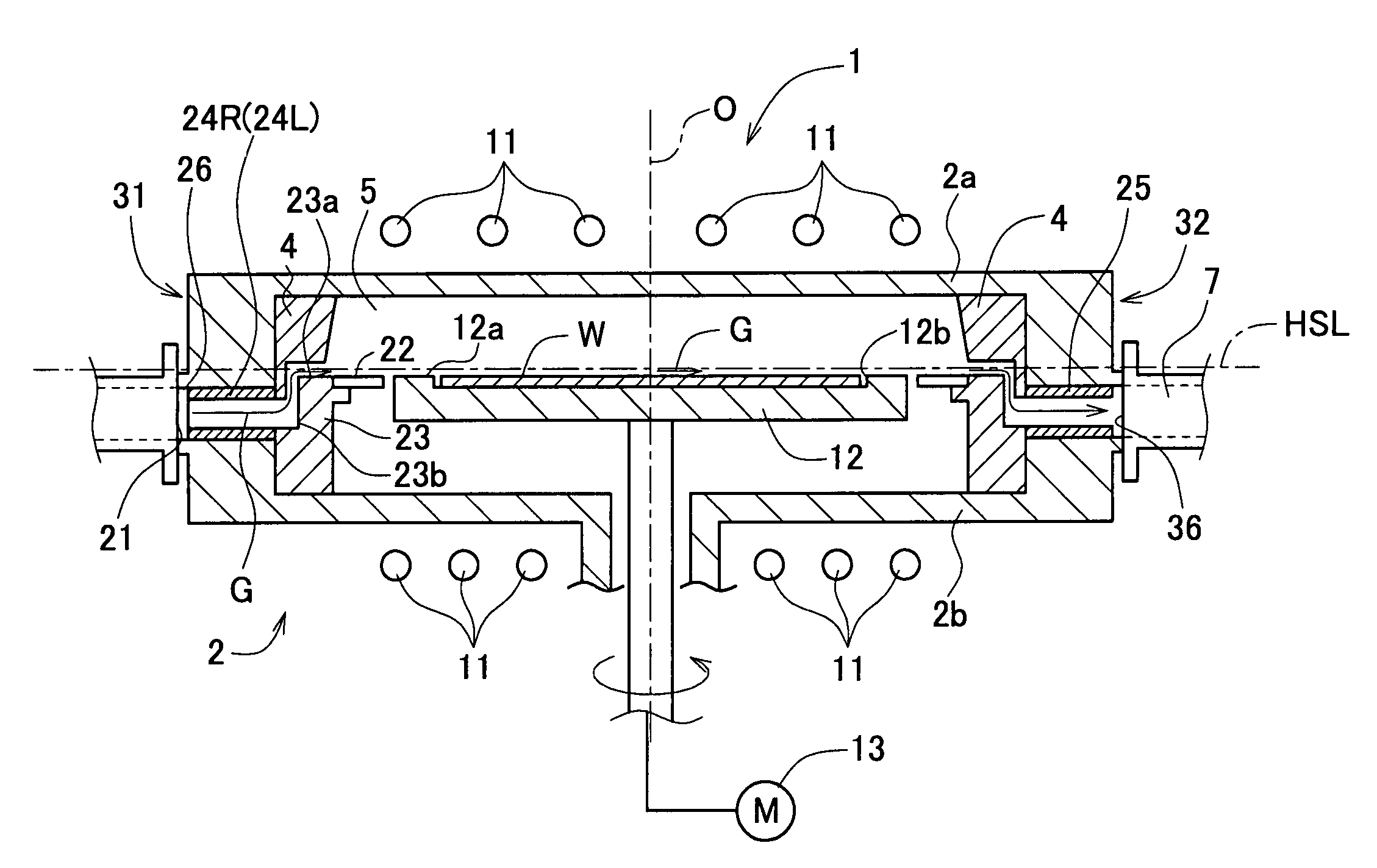
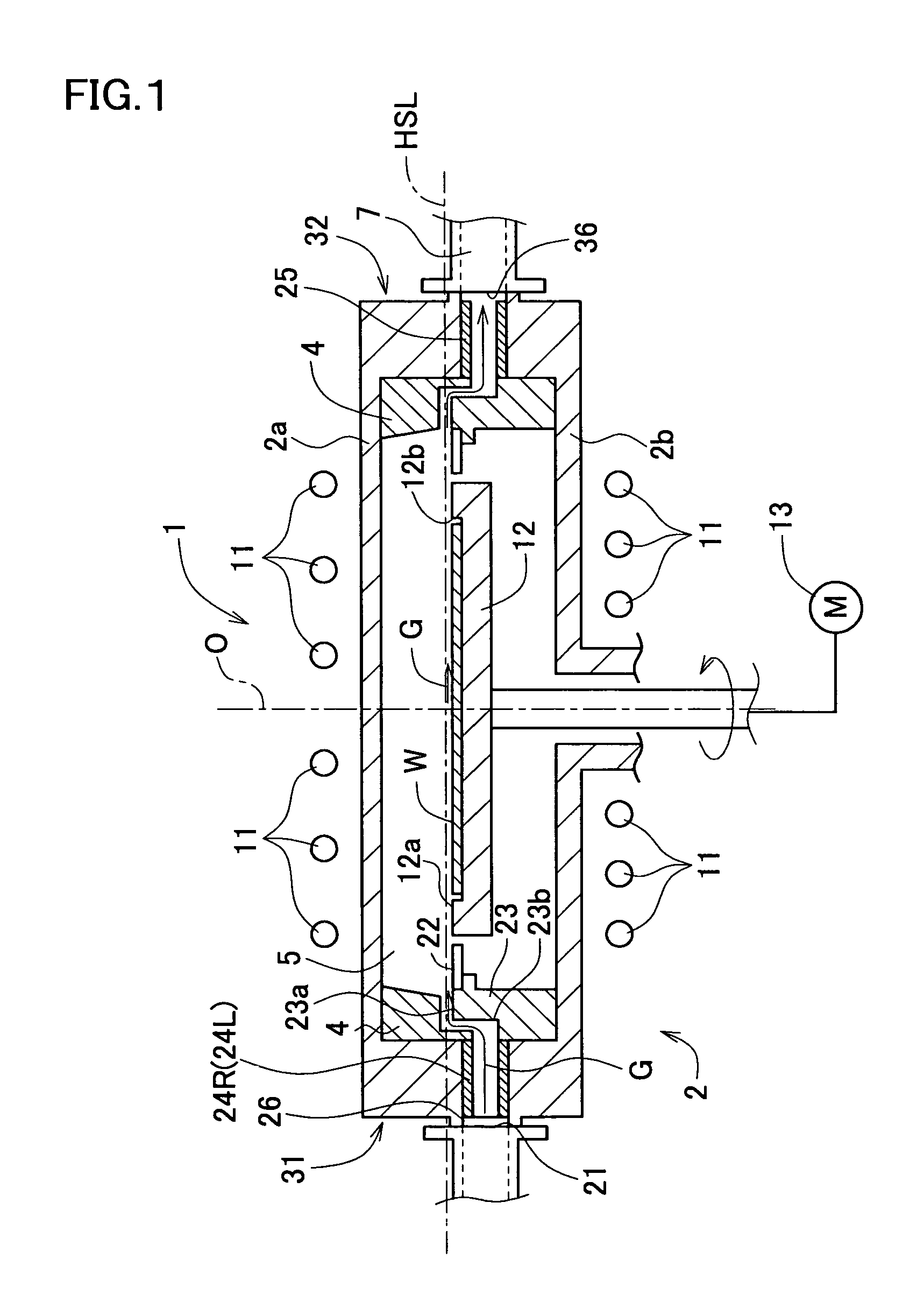
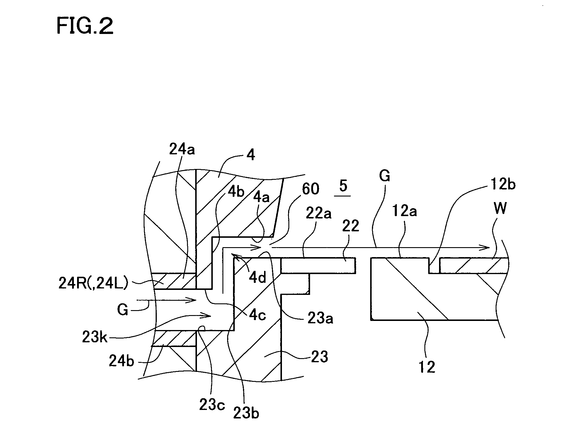
[0066]A flow route of the source gas in the vapor phase growth apparatus 1 as shown in FIGS. 1 to 4 was found by computer simulation. For the comparative purpose, also a flow route of the source gas in the conventional vapor phase growth apparatus having an unimproved upper lining component was found. Also a growth rate distribution of the silicon single crystal film when it was epitaxially grown on the silicon single crystal substrate in the vapor phase growth apparatus 1 shown in FIGS. 1 to 4 was estimated by computer simulation. For the comparative purpose, also a growth rate distribution of the silicon single crystal film when it was epitaxially grown on the silicon single crystal substrate in the conventional vapor phase growth apparatus was estimated. Set conditions were as listed below.[0067]Software: Fluent Ver 6.0 (product of Fluent Asia Pacific Co., Ltd.)[0068](Dimensions)[0069]Inner diameter of bank component=300 mm[0070]R3 of upper lining...


PUM

PropertyMeasurementUnit
diameteraaaaaaaaaa
diameteraaaaaaaaaa
lengthaaaaaaaaaa

Abstract

Material gas hits the outer peripheral surface of a dam member and rides on the upper surface side, and then is allowed to flow along the main surface of a silicon single-crystal substrate placed on a susceptor. An upper lining member is disposed above the dam member so as to face the dam member. A gas introducing clearance is formed between the dam member and the upper lining member. In a vapor growth device, the upper lining member is regulated in size so that the length, formed in a direction along the horizontal reference line, of the gas introducing clearance gradually decreases as it is away from the horizontal reference line or is kept constant at any position. A vapor growth device capable of making more uniform the flowing route of a material gas flowing on the silicon single-crystal substrate, and a production method for an epitaxial wafer are provided.

Description

BACKGROUND OF THE INVENTION[0001]1. Field of the Invention[0002]This invention relates to a vapor phase growth apparatus allowing vapor phase growth of a silicon single crystal film on the main surface of a silicon single crystal substrate to proceed therein, and a method of fabricating an epitaxial wafer realized using the same.[0003]2. Description of the Related Art[0004]Silicon epitaxial wafer having a silicon single crystal film (simply referred to as “film”, hereinafter) grown in vapor phase on the main surface of a silicon single crystal substrate (simply referred to as “substrate”, hereinafter) is widely used for electronic devices such as bipolar IC, MOS-IC and so forth. With advancement in micronization of the electronic devices, requirement for flatness of the main surface of the epitaxial wafer in which the devices are fabricated has been becoming more stringent. Causal factors affecting the flatness include flatness of the substrate and distribution of the film thickness...

Claims


Application Information

Patent Timeline
Patent Type & Authority Patents(United States)
IPC IPC(8): H01L21/20C23C16/24C23C16/455C30B25/14C30B29/06H01L21/205
CPCC23C16/455C30B25/14Y10T117/10C30B29/06C23C16/45587C23C16/24
Inventor YAMADA, TORU
Owner SHIN-ETSU HANDOTAI CO LTD
Why Eureka
Try Eureka