
Crest factor reduction for brand-limited multi-carrier signals

a multi-carrier signal and crest factor technology, applied in the field of signal processing, can solve the problems of unbalanced multi-carrier signal, poor performance of windowing method, unsuitable post-processing multi-carrier modulated signal method, etc., and achieve the effect of reducing the peak-to-average power (par) ratio of signal and increasing out-of-band emissions

Active Publication Date: 2015-01-20
SCINTERA NETWORKS +1
View PDF9 Cites 8 Cited by
  • Summary
  • Abstract
  • Description
  • Claims
  • Application Information

AI Technical Summary

Benefits of technology

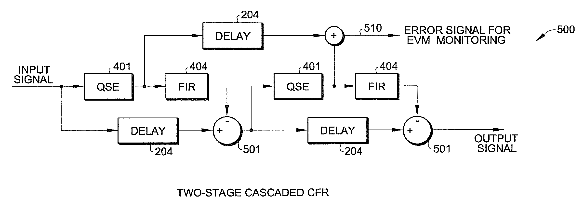
The solution achieves near-optimum CFR performance with low computational complexity, resulting in low-power and compact digital circuit implementations that effectively reduce the PAR of signals like LTE, achieving 6.0 dB with 6.5% error-vector-magnitude (EVM) or 6.7 dB with 4.3% EVM, outperforming previous solutions.

Problems solved by technology

However, many of these methods require modifications of either the data symbols used or the modulation schemes.
Such methods are unsuitable for post-processing multi-carrier modulated signals for CFR, because the data symbols and modulation details are not available for the CFR processor.
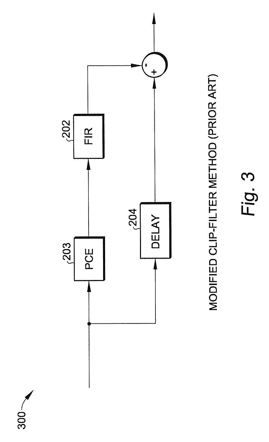
One method that is suitable for multi-carrier signals is known as the “windowing method.” However, the windowing method performs poorly due to fundamental drawbacks in the algorithm.
The flat magnitude response requirement renders the method not suitable for unbalanced multi-carrier signals, because low-power carriers suffer more error-vector-magnitude (EVM) degradation than high-power carriers.
However, the finite impulse response (FIR) filters required for this method typically involve a large number of taps.
Such filters consume high power and require large silicon areas in a conventional FIR design.
The improvement, however, increases slowly with each additional stage, which makes it difficult to achieve the desired performance under real-world constraints on power consumption and chip area.
First, such methods result in circuits that have high power consumption requirements, due to their computational complexity.
Second, such methods result in circuits that have relatively low performance.
The low computational complexity results in digital circuit implementations that are low-power and have a relatively small footprint.

Method used


Image

  • Crest factor reduction for brand-limited multi-carrier signals
  • Crest factor reduction for brand-limited multi-carrier signals
  • Crest factor reduction for brand-limited multi-carrier signals

Examples


Embodiment Construction

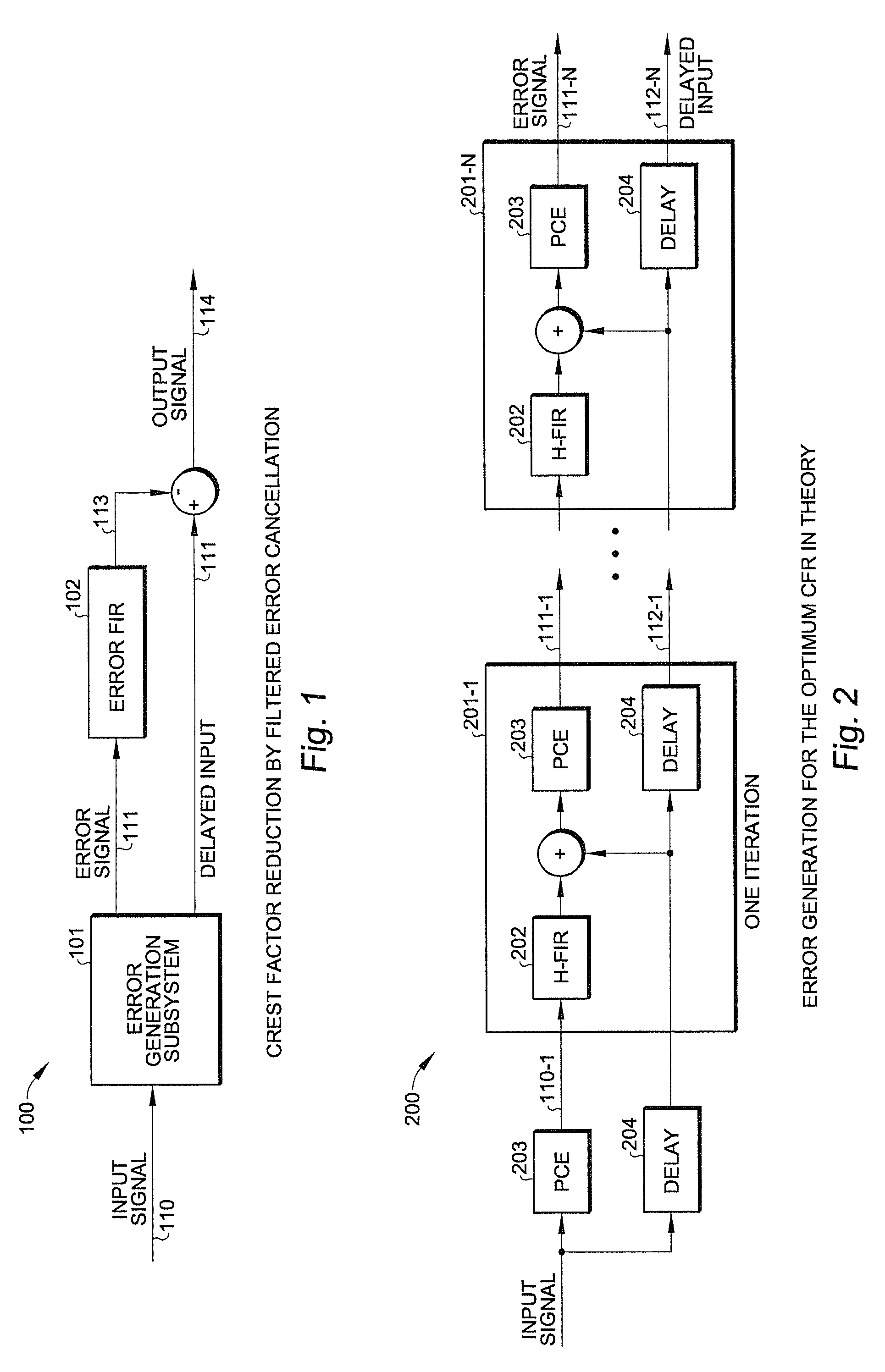
[0036]According to one embodiment of the present invention, crest factor reduction (CFR) of a digitally modulated signal in complex baseband is achieved by post-processing of the input signal. The present invention is applicable, for example, to an input signal that, as seen in the frequency domain, has a signal band that is divided into a number of non-overlapping subbands or carriers, with each carrier having its own multiple-access modulation format. Such an input signal is used in, for example, WCDMA or LTE signals of 3G / 4G wireless systems.

[0037]The present invention takes advantage of a procedure that solves for an optimum CFR using a constraint-optimization approach. In this approach, the CFR-induced distortion is measured using a weighted mean square error (MSE) adapted for use with arbitrary multi-carrier signals. The optimum CFR may result from a procedure that either minimizes the crest factor, subject to a constraint on the weighted MSE, or minimizes the weighted MSE sub...


PUM


Abstract

A crest factor reduction (CFR) circuit reduces the peak-to-average (PAR) power of a digitally modulated signal in a complex baseband is achieved by post-processing the input signal, with negligible increase in out-of-band emissions. The CFR circuit takes advantage of a procedure that solves for an optimum CFR using a constraint-optimization approach. In one embodiment, the CFR circuit, which receives an input signal and provides an output signal, includes: (a) an error generation circuit that receives the input signal and provides an error signal representative of a measure of circuit-induced distortion and a delayed input signal, the delayed input signal being the input signal delayed by a predetermined value; (b) a linear-phase filter receiving the error signal to provide a correction signal; and (c) a summer that subtracts the correction from the delayed input signal to provide the output signal. This circuit can achieve near optimal CFR for arbitrary multi-carrier signals without incurring high computational complexity.

Description

BACKGROUND OF THE INVENTION[0001]1. Field of the Invention[0002]The present invention relates to signal processing. In particular, the present invention relates to applying crest factor reduction techniques to a digitally modulated signal used in communication application.[0003]2. Discussion of the Related Art[0004]The crest factor of a modulated signal is the square root of the signal's peak-to-average power ratio (PAR). Signals with large crest factor are widely used in communication systems. In many 4G / 4G communication systems (e.g. WCDMA or LTE), when seen in the frequency domain, the signal band is divided into a number of non-overlapping sub-bands or carrier signals, with each carrier signal having its own multiple-access modulation format. The sampling rate of the signal is typically higher than the Nyquist rate, i.e. the signal's double-side bandwidth. In such systems, crest factor reduction (CFR) improves power efficiency in a wireless transmitter.[0005]In the prior art, va...

Claims


Application Information

Patent Timeline
Patent Type & Authority Patents(United States)
IPC IPC(8): H04B1/04H04B1/10H03H7/30
CPCH04B1/0475H03H17/00H04L27/2624
Inventor YU, QIANWANG, YANKRISHNAMOORTHY, RAJEEV
Owner SCINTERA NETWORKS
Learn More