Ultrasensitive biological and chemical detection using surface plasmon resonance

a surface plasmon resonance and biological and chemical detection technology, applied in the field of optical sensing, can solve the problems of chemical samples, inability to detect biological samples, etc., to achieve the effect of reducing the noise floor, reducing the noise of baseline, and eliminating the contribution of undesired

Inactive Publication Date: 2015-02-24
IBM CORP
View PDF16 Cites 0 Cited by
  • Summary
  • Abstract
  • Description
  • Claims
  • Application Information

AI Technical Summary

Benefits of technology

[0031]The method of optical sensing, and an associated apparatus, of the present invention offers the advantage of being both label-free (e.g., free of fluorescent tags) and having considerably lower baseline noise than alternative label-free techniques. Since detection is directly related to the signal to noise ratio, reduction of the noise floor increases precision and can be used to achieve detection at the lower concentrations present during early stages of disease. Further, the method and apparatus of the present invention can be used in a unique self-referencing configuration to eliminate the undesired contribution of non-specific interfacial adsorption (e.g., serum proteins), making the apparatus particularly useful for ultrasensitive measurements in the presence of complex media (e.g., blood).

Problems solved by technology

Unfortunately, the number of available treatment options and the overall prognosis decrease considerably as the disease progresses from early to advanced stages.
Further, many diseases are asymptomatic until the advanced stages, at which point options are limited.
While these labeled methods typically provide adequate signal-to-noise ratio, the production of labeled antibodies is expensive, time consuming, and can influence molecular binding.
Further, since the sandwich assay requires multiple incubation steps, these assays do not permit real-time detection.
While this is an impressive achievement, there are a number of disadvantages with the experimental setup of Li et al.
One important disadvantage relates to the sensitivity of the apparatus.
However, operating at minimum reflection where only a small percentage of photons reach the detector severely reduces the signal-to-noise ratio.
Increasing laser power is also not a viable option, since the adsorbed photons dissipate as heat in the dielectric material of interest and at high powers can create temperature gradients in the sample.
In addition, there is an extremely narrow dynamic range for phase detection.
For real-world applications, such as detection in serum, non-specific adsorption alone would likely cause departure from the usable detection range.

Method used


Image

  • Ultrasensitive biological and chemical detection using surface plasmon resonance
  • Ultrasensitive biological and chemical detection using surface plasmon resonance
  • Ultrasensitive biological and chemical detection using surface plasmon resonance

Examples


first embodiment

[0051]FIG. 2A depicts adjacent streams 31 and 33 within a single channel of a fluid cell at a first position 36 corresponding to an initial time and a second position 37 corresponding to a later time, in accordance with embodiments of the present invention. At the first position 36, the adjacent streams 31 and 33 are separate streams because insufficient time has elapsed for mixing of the streams to occur, as depicted in the projection 38 of the adjacent streams 31 and 33. At the second position 37, a mixed fluid region 32 has formed between the adjacent streams 31 and 33 due to turbulent mixing of the adjacent streams 31 and 33, as depicted in the projection 39 of the streams 31, 32, and 33.

[0052]FIG. 2B depicts adjacent streams 41 and 43 within a flow cell 45, in accordance with embodiments of the present invention. The flow cell 45 has channel dimensions for achieving a low Reynolds number that produces laminar flow (i.e., flow having a Reynold's number less than 2000) under whic...

second embodiment

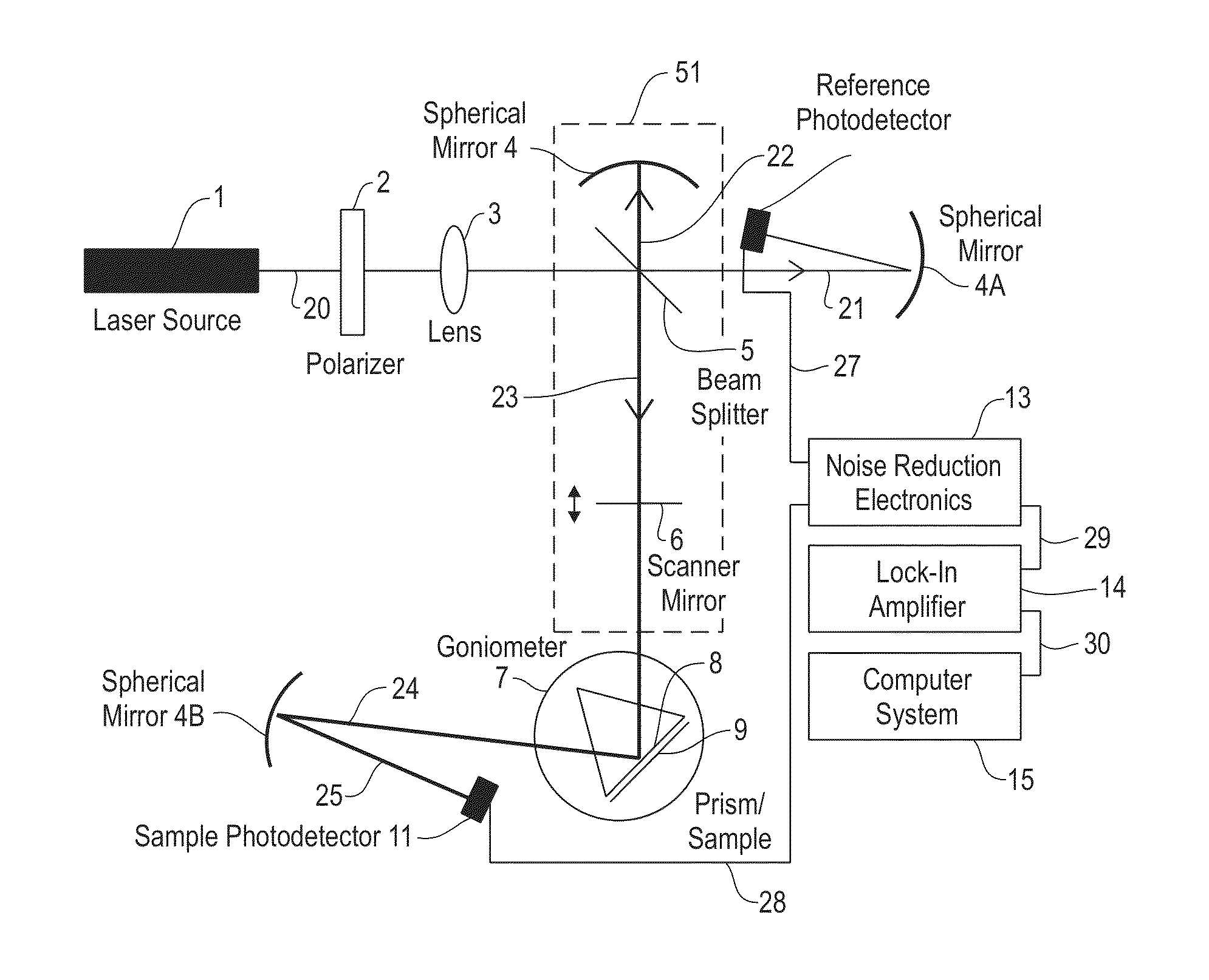
[0073]FIG. 4A depicts a top view of an apparatus or device comprising an optical system 52 that includes a polarizing beam splitter 63 for alternately directing a scanning beam 20 from a laser 1 onto a sample channel and a reference channel of a flow cell 9, in accordance with embodiments of the present invention. In one embodiment, the fluid in the sample channel and the fluid in the reference channel are essentially separated from each other. FIG. 4B depicts a vertical cross section of the optical system 52 of FIG. 4A, in accordance with embodiments of the present invention.

[0074]The scanning beam 20 includes a laser noise component whose amplitude reflects the spurious noise (i.e., in excess of the shot noise) generated in the laser 1. The scanning beam 20, after passing through a polarizer 2, is split by a beam splitter 5 into a reference beam 21 and a sample beam 26. Both the reference beam 21 and the sample beam 22 include the laser noise component of the scanning beam 20.

[007...


PUM

PropertyMeasurementUnit
operating frequenciesaaaaaaaaaa
Reynolds numberaaaaaaaaaa
frequencyaaaaaaaaaa

Abstract

A device, including sample and reference channels through which first and second solutions flow, respectively, the first solution including an analyte, the channels having a metal film in contact with the first and second solutions, the metal film configured with a linker to selectively bind the analyte; a light source whose output is modulated by an optical system, so that light is directed from the optical system alternately towards the sample and reference channels, surface plasmons within the metal film being created; a first photodetector that monitors the strength of the output from the light source; a second photodetector that collects optical signals reflected from the metal film; electronics that monitors output from the first and the second photodetectors, thereby detecting a noise-compensated difference in signals from the two channels; and a computer processor that determines, from analysis of the noise-compensated difference, presence of the analyte in the first solution.

Description

[0001]This invention was made with government support under ECCS-0823827 awarded by the National Science Foundation. The government has certain rights in the invention.FIELD OF THE INVENTION[0002]The present invention relates to a method of optical sensing, and an associated apparatus, using surface plasmon resonance (SPR) to achieve ultrasensitive interfacial detection of gas and solution-phase biological and chemical analytes.BACKGROUND OF THE INVENTION[0003]Biosensors directed towards disease and cancer detection often target biomarkers such as proteins that are not present in healthy individuals. The buildup of these biomarkers correlates with the progression of the particular disease. Unfortunately, the number of available treatment options and the overall prognosis decrease considerably as the disease progresses from early to advanced stages. Further, many diseases are asymptomatic until the advanced stages, at which point options are limited. For these reasons, early detectio...

Claims


Application Information

Patent Timeline
Patent Type & Authority Patents(United States)
IPC IPC(8): G01N21/00G01N21/05G01N21/27G01N21/552
CPCG01N21/05G01N21/553G01N21/274
Inventor FELLER, ROBERT E.KNOESEN, ANDREMILLER, ROBERT D.
Owner IBM CORP
Why Eureka
Try Eureka