
Gas diffusion layer for fuel cell, manufacturing method therefor, membrane electrode assembly, and fuel cell

a technology of gas diffusion layer and fuel cell, which is applied in the field of fuel cell, can solve the problems of deterioration of the polymer electrolyte membrane, difficulty in reducing the cost of the electrode layer, and increase the cost of material and manufacturing process, so as to improve the power generation performance, reduce the cost of the electrode layer, and high voltage

Active Publication Date: 2015-04-07
PANASONIC CORP
View PDF33 Cites 0 Cited by
  • Summary
  • Abstract
  • Description
  • Claims
  • Application Information

AI Technical Summary

Benefits of technology

[0046]With the gas diffusion layer for fuel cell according to the first aspect of the present invention, because the gas diffusion layer is structured with the porous member mainly comprised of the conductive particles and the polymer resin, without the use of a carbon fiber base member, a reduction in costs of the fuel cell, can be achieved. Further, adjustment of the porosity or the thickness makes it possible to improve the power generation performance, which makes it possible to obtain a high voltage even under low-humidity drive.
[0047]With the gas diffusion layer according to the second aspect of the present invention, because it is structured with the porous member mainly comprised of the conductive particles and the polymer resin, with added carbon fibers by a weight smaller than a weight of the polymer resin, and without the use of a carbon fiber base member, a reduction in costs of the fuel cell can be achieved. Further, because such addition of carbon fibers can increase the strength as the gas diffusion layer, it becomes possible to reduce the mix amount of the polymer resin acting as a binder. This makes it possible to reduce the mix ratio of the polymer resin functioning as an insulator, whereby an improvement in the power generation performance can be achieved.

Problems solved by technology

Accordingly, it suffers from an issue that the inside of the electrode layer becomes dry due to gas diffusion, increasing the resistance in relation to proton conductivity of the polymer electrolyte membrane, whereby the voltage drops.
Further, because the carbon fiber base member is expensive, it is difficult to reduce the cost of the electrode layer.
Further, with the structure of the embodiment of Patent Document 2, because a mesh sheet is used as the structure body in order to secure strength, it suffers from an issue of an increase in the material cost and complication of the manufacturing process.
Still further, because a metal mesh is used as the mesh sheet in the structure of the embodiment of Patent Document 2, metal powder of the metal mesh may attach to the electrode layer, which may invite deterioration of the polymer electrolyte membrane, impairing durability of the fuel cell.
Because PTFE is an insulator, the high mix ratio of PTFE fails to achieve sufficient electric conductivity, whereby the power generation performance may be impaired.
Further, also in a case where an insulator such as ceramic or engineering plastic is used as a mesh sheet, sufficient electric conductivity may not be achieved, and the power generation performance may be impaired.

Method used


Image

  • Gas diffusion layer for fuel cell, manufacturing method therefor, membrane electrode assembly, and fuel cell
  • Gas diffusion layer for fuel cell, manufacturing method therefor, membrane electrode assembly, and fuel cell
  • Gas diffusion layer for fuel cell, manufacturing method therefor, membrane electrode assembly, and fuel cell

Examples


first embodiment

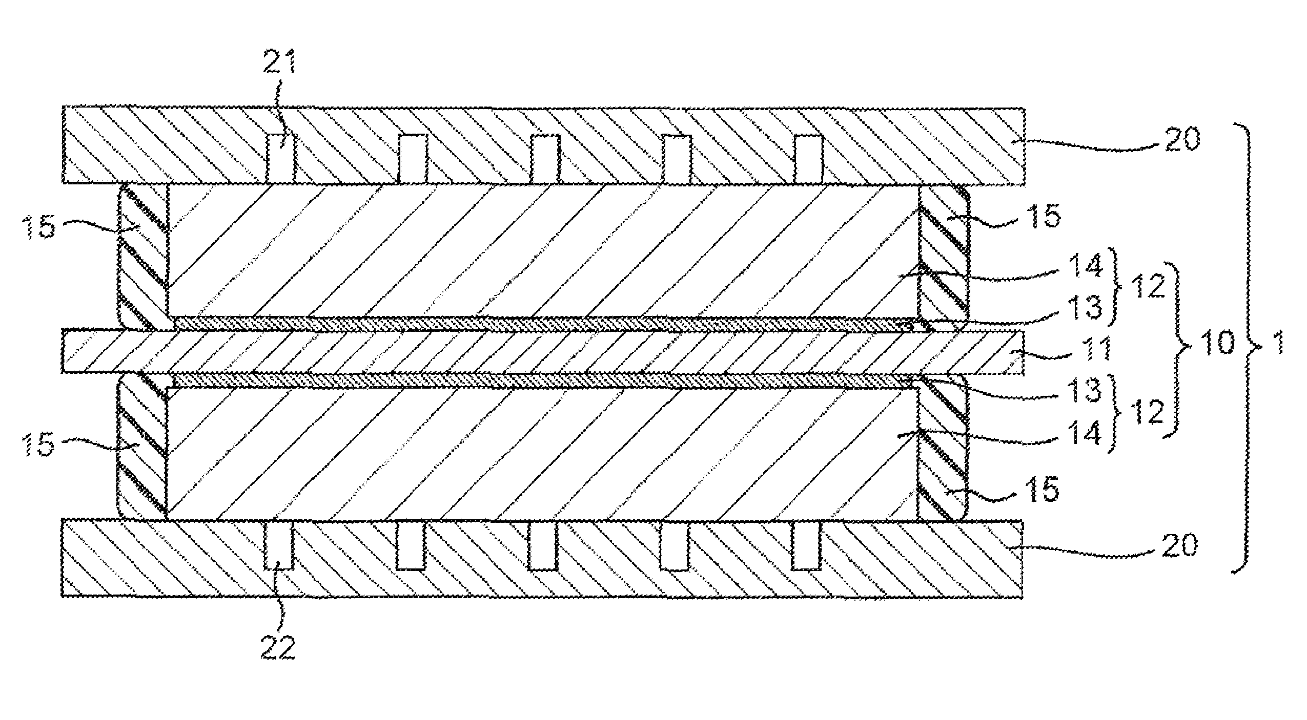
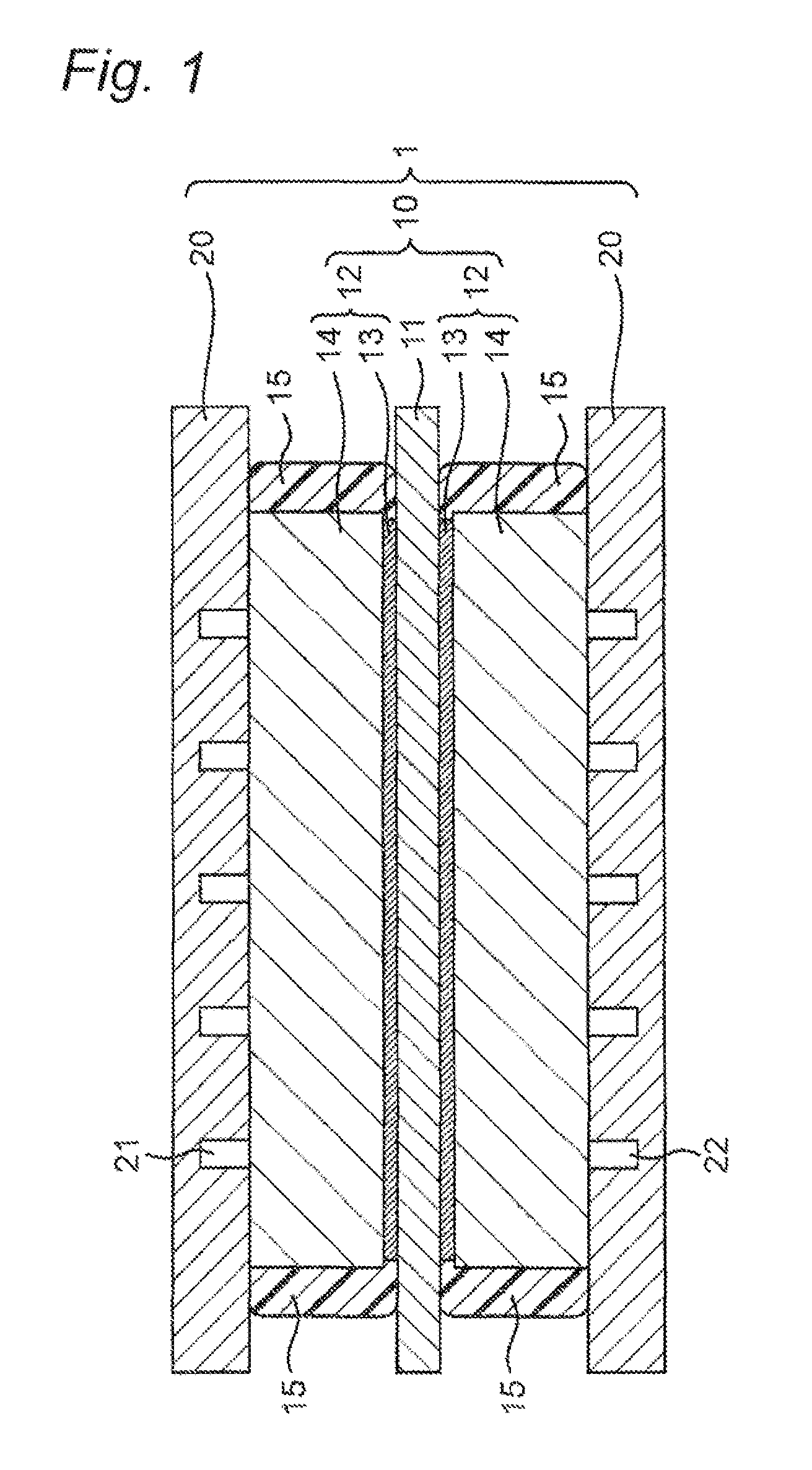
[0057]With reference to FIG. 1, a description will be given of the basic structure of a fuel cell according to a first embodiment of the present invention. FIG. 1 is a cross-sectional view showing the basic structure of the fuel cell according to the first embodiment. The fuel cell according to the first embodiment is a polymer electrolyte fuel cell that allows a fuel gas containing hydrogen and an oxidant gas containing oxygen such as air to electrochemically react with each other, to produce electric power and heat at the same time. It is noted that the present invention is not limited to such a polymer electrolyte fuel cell, but is applicable to various fuel cells.

[0058]As shown in FIG. 1, the fuel cell according to the first embodiment includes a cell 1 including a membrane electrode assembly 10 (hereinafter referred to as the MEA: Membrane-Electrode-Assembly) and paired plate-like conductive separators 20 and 20 disposed on opposite faces of the MEA 10. It is noted that the fue...

second embodiment

[0138]A description will be given of a fuel cell according to a second embodiment of the present invention. The fuel cell according to the second embodiment is different from the fuel cell according to the first embodiment in that carbon fibers of a weight not qualifying as a base member are added to the gas diffusion layer 19. The other aspects are the same as the first embodiment and, accordingly, the description common to them is not repeated, and the description will be given chiefly of the difference.

[0139]The gas diffusion layer according to the second embodiment is structured with a sheet-like and rubber-like porous member mainly comprised of conductive particles and polymer resin, with added carbon fibers of a weight not qualifying as a base member (e.g., of a weight smaller than the conductive particles and the polymer resin).

[0140]Example materials of the carbon fibers may include vapor grown carbon fibers (hereinafter referred to as VGCFs) milled fibers, cut fibers, chopp...


PUM

PropertyMeasurementUnit
weight percentaaaaaaaaaa

Abstract

A gas diffusion layer for fuel cell of the present invention is structured with a porous member mainly comprised of conductive particles such as acetylene black, graphite and a polymer resin such as PTFE. This makes it possible to achieve both an improvement in power generation performance of the fuel cell and a reduction in costs.

Description

TECHNICAL FIELD[0001]The present invention relates to a fuel cell, in which a liquid fuel such as pure hydrogen, methanol or the like, or a reducing agent such as reformed hydrogen obtained from a fossil fuel, is used as a fuel gas, and air (oxygen) is used as an oxidant gas. In particular, the present invention relates to a gas diffusion layer included in a membrane electrode assembly used for the fuel cell, and a manufacturing method thereof.BACKGROUND ART[0002]A fuel cell, for example a polymer electrolyte fuel cell, is an apparatus that allows a fuel gas containing hydrogen and an oxidant gas containing oxygen such as air to electrochemically react with each other at a gas diffusion layer that has a catalyst layer such as platinum, such that electric power and heat are produced at the same time.[0003]FIG. 7 is a schematic diagram showing the basic structure of a conventional polymer electrolyte fuel cell. A single cell (also referred to as a cell) 100 of the polymer electrolyte ...

Claims


Application Information

Patent Timeline
Patent Type & Authority Patents(United States)
IPC IPC(8): H01M8/04H01M8/00B28B3/12H01M8/02H01M8/10
CPCH01M8/1002H01M8/0234H01M8/0239H01M8/0243H01M2008/1095Y02E60/521H01M8/1007Y02E60/50Y02P70/50
Inventor YAMAUCHI, MASAKITSUJI, YOICHIRO
Owner PANASONIC CORP
Learn More