On-board directional flat-plate antenna, vehicle comprising such an antenna, and satellite telecommunication system comprising such a vehicle

a flat-plate antenna and directional antenna technology, applied in the field of satellite telecommunication system comprising such a vehicle, can solve the problems of crippling the cost and complexity of antennas for an application to transport means, too large for future high-speed trains, and low transmission bitrate for communications. , to achieve the effect of low cost, simple implementation and compact heigh

Inactive Publication Date: 2015-04-21
THALES SA
View PDF7 Cites 13 Cited by
  • Summary
  • Abstract
  • Description
  • Claims
  • Application Information

AI Technical Summary

Benefits of technology

[0011]A first aim of the invention is to produce an onboard directional plane antenna not comprising the drawbacks of the existing antennas and that may be installed on a mobile transport means. In particular, the aim of the invention is to produce an onboard directional plane antenna, operating in the Ka-band, which is very compact height-wise, simple to implement and of low cost, and capable of remaining pointed at a satellite continuously whatever the position of the transport means and allowing control of the polarization plane without the addition of an orientable grid.

Problems solved by technology

The problem is that in the L-band there are very few frequencies available and that the transmission bitrate for the communications is therefore very low.
The obstacles may be vegetation or infrastructures such as buildings or bridges.
These array antennas have the advantage of being plane and therefore of small size height-wise, however the angular domain to be covered being very large, in order to obtain good performance and avoid the appearance of array lobes in the antenna radiation pattern, it is necessary to use a beamforming array comprising a very large number of phase controls, this being prohibitive.
For example, for an antenna in the Ku-band having an area of the order of 1 m2, the number of radiating elements of the antenna must be greater than 15000, this being crippling in terms of antenna cost and complexity for an application to transport means.
Although this height is compatible with present-day trains, it is too large for future high-speed trains with two decks for which the height available for the installation of an antenna, between the roof of the train and the catenaries, is much smaller.
For example, the present-day reflector-type antennas installed on airplanes have a height of the order of 30 cm and give rise to extra fuel consumption equivalent to eight additional passengers.
However, this antenna operating initially under linear polarization, it is necessary to supplement it with an additional orientable polarization grid mounted on the upper face of the antenna so as to control the plane of polarization of the antenna, thereby increasing the complexity of implementation and the height of the antenna which is then not plane.
Scanning and squinting of the beam in elevation, in a plane perpendicular to the plane of the antenna, is obtained by switching the various sources, but no modification of pointing in azimuth is possible.
Moreover, this type of very compact antenna exhibits the drawback of requiring high-power switching means, this never being simple to achieve.
Furthermore, the switching of the sources is discrete, thus not making it possible to obtain continuous pointing of the beam.
Finally, this very compact antenna is fed by a unique power source, thereby making it necessary to use bulky power amplifiers which considerably increase the bulkiness of the antenna which becomes too large for an application to transport means.

Method used


Image

  • On-board directional flat-plate antenna, vehicle comprising such an antenna, and satellite telecommunication system comprising such a vehicle
  • On-board directional flat-plate antenna, vehicle comprising such an antenna, and satellite telecommunication system comprising such a vehicle
  • On-board directional flat-plate antenna, vehicle comprising such an antenna, and satellite telecommunication system comprising such a vehicle

Examples


Embodiment Construction

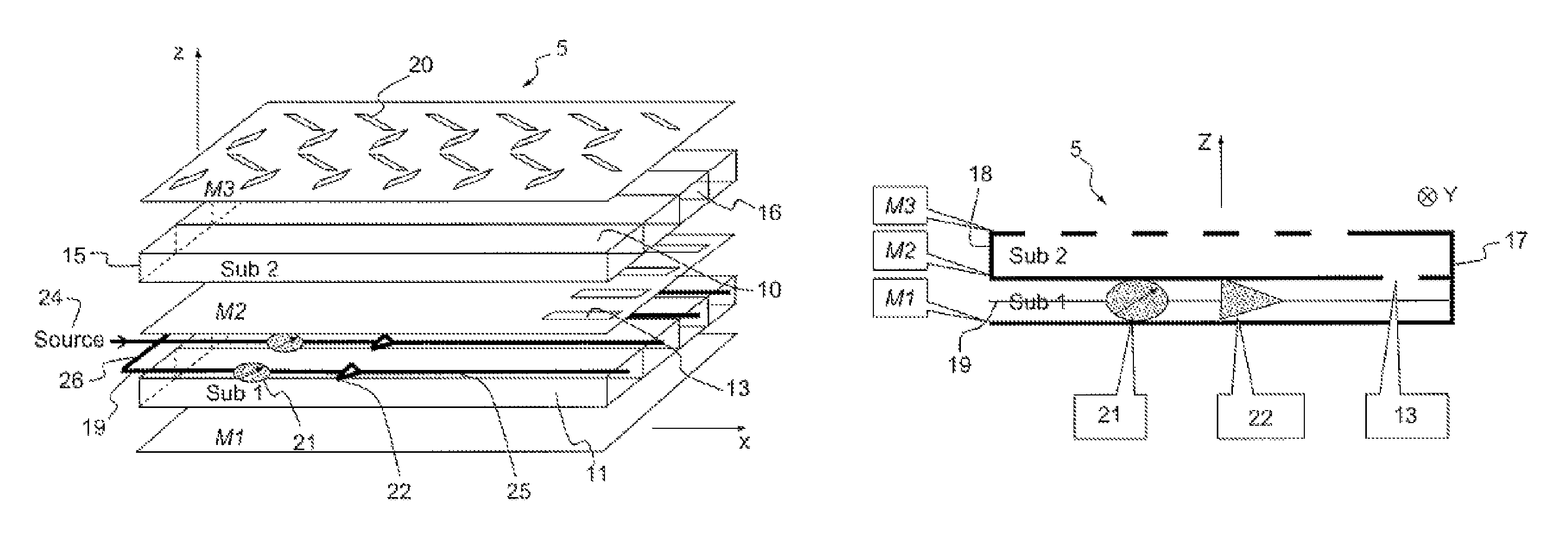
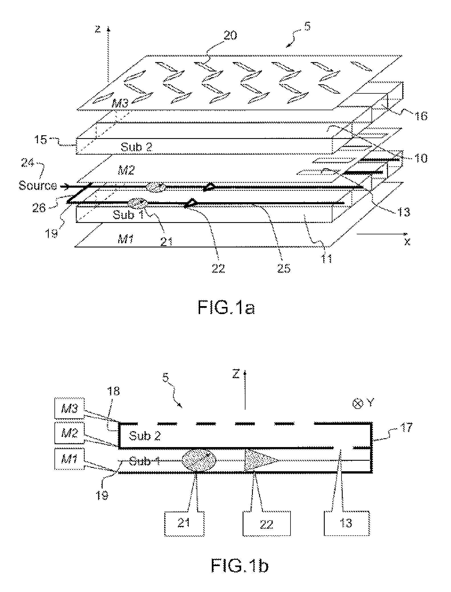
[0025]The plane antenna represented partially in FIGS. 1a and 1b is of tri-plate structure. It comprises an array 5 of radiating-slot waveguides comprising an alternating succession of three metallic plates M1, M2, M3 respectively lower, intermediate and upper, superposed in parallel one above the other, and of two dielectric substrates Sub1, Sub2, respectively lower and upper, inserted between two consecutive metallic plates. The planes of the various layers of the antenna are parallel to a plane XY. The height of the antenna is along an axis Z orthogonal to the XY plane. The upper dielectric substrate Sub2 supports the radiating-slot waveguides 10, and the lower substrate Sub1 supports waveguides 11 intended to individually feed each radiating-slot waveguide 10 via a microwave signal. The antenna having to operate in the Ka-band, in order to comply with the standards imposed in this operating domain, it must emit waves under a circular polarization. Therefore, according to the inv...


PUM


Abstract

An onboard directional plane antenna comprises at least one array of radiating-slot waveguides comprising an alternating succession of three superposed metallic plates and of two dielectric substrates. The two substrates each comprise at least four adjacent waveguides, corresponding and communicating with one another pairwise by way of coupling slots. Each waveguide of the upper substrate furthermore comprises a plurality of radiating slots passing through the upper metallic plate, all the radiating slots of one and the same waveguide being parallel to one another and oriented in one and the same direction, the radiating slots of two adjacent waveguides being disposed in chevrons. Each waveguide of the lower substrate comprises an internal individual feed circuit comprising an individual electronic circuit for phase shifting and amplification.

Description

CROSS-REFERENCE TO RELATED APPLICATIONS[0001]This application is a National Stage of International patent application PCT / EP2011 / 051105, filed on Jan. 27, 2011, which claims priority to foreign French patent application No. FR 1000474, filed on Feb. 5, 2010, the disclosures of which are incorporated by reference in their entirety.FIELD OF THE INVENTION[0002]The present invention relates to an onboard directional plane antenna, a vehicle comprising such an antenna and a satellite telecommunication system comprising such a vehicle. It applies notably to the field of satellite-based telecommunications and more particularly to telecommunication equipment installed on mobile vehicles such as terrestrial, maritime or aeronautical means of transport so as to ensure a bi-directional Ka-band connection between a mobile terminal and a terrestrial station by way of a repeater installed on a satellite. According to a particular embodiment, it also applies to the simultaneous tracking of two dis...

Claims


Application Information

Patent Timeline
Patent Type & Authority Patents(United States)
IPC IPC(8): H01Q13/10H01Q21/24H01Q21/00
CPCH01Q21/0043H01Q21/005H01Q21/24H04B7/18508
Inventor LENORMAND, REGISDENIS, XAVIERDECROIX, JACQUESCHUBERRE, NICOLASRIGAL, CHRISTIANGARNIER, GILLESALMEIDA, JEAN-LUC
Owner THALES SA
Why Eureka
Try Eureka