Prosthetic heart valve devices, prosthetic mitral valves and associated systems and methods

a technology of prosthetic heart valves which is applied in the field of prosthetic heart valve devices and prosthetic mitral valves, can solve the problems of valve leaflets prolapse difficult coapting of leaflets during systole, and abnormal leakage of blood from the left ventricle into the left atrium

Active Publication Date: 2015-05-26
TWELVE
View PDF673 Cites 271 Cited by
  • Summary
  • Abstract
  • Description
  • Claims
  • Application Information

AI Technical Summary

Problems solved by technology

Mitral valve regurgitation is a disorder of the heart in which the leaflets of the mitral valve fail to coapt into apposition at peak contraction pressures, resulting in abnormal leaking of blood from the left ventricle into the left atrium.
Enlargement of the mitral annulus makes it difficult for the leaflets to coapt during systole.
A ruptured chordae tendineae, for example, may cause a valve leaflet to prolapse into the left atrium due to inadequate tension on the leaflet.
As the left ventricle contracts during systole, the affected papillary muscles do not contract sufficiently to effect proper closure.
Mitral valve prolapse, or when the mitral leaflets bulge abnormally up in to the left atrium, causes irregular behavior of the mitral valve and may also lead to mitral valve regurgitation.
These invasive procedures are conventionally done through large open thoracotomies and are thus very painful, have significant morbidity, and require long recovery periods.
However, with many repair and replacement procedures, the durability of the devices or improper sizing of annuloplasty rings or replacement valves may result in additional problems for the patient.
Moreover, many of the repair procedures are highly dependent upon the skill of the cardiac surgeon where poorly or inaccurately placed sutures may affect the success of procedures.
Mitral valve replacement, compared with aortic valve replacement, poses unique anatomical obstacles, rendering percutaneous mitral valve replacement significantly more challenging than aortic valve replacement.
First, unlike the relatively symmetric and uniform aortic valve, the mitral valve annulus has a non-circular D-shape or kidney-like shape, with a non-planar,...

Method used


Image

  • Prosthetic heart valve devices, prosthetic mitral valves and associated systems and methods
  • Prosthetic heart valve devices, prosthetic mitral valves and associated systems and methods
  • Prosthetic heart valve devices, prosthetic mitral valves and associated systems and methods

Examples


examples

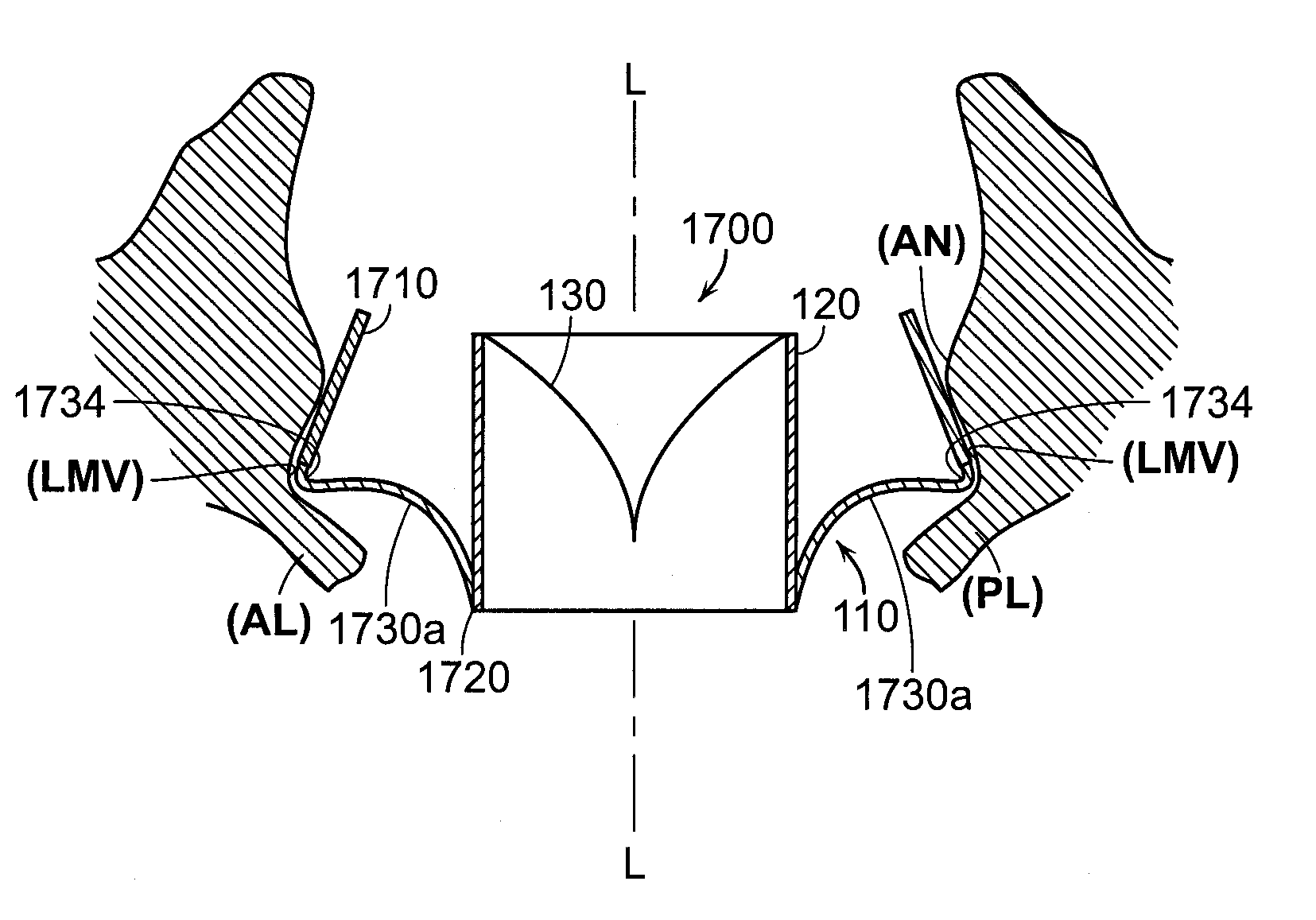
[0392]1. A prosthetic heart valve device, comprising:[0393]a valve support having an upstream region and a downstream region relative to blood flow through a native heart valve of a human heart, the upstream region being configured to support a prosthetic valve, the prosthetic valve having a plurality of leaflets and having an undeformed shape in which the leaflets coapt sufficiently to prevent backflow through the prosthetic valve;[0394]an anchoring member having a longitudinal dimension and including a tissue fixation portion, an integration region coupled to the valve support, and a plurality of lateral connectors between the tissue fixation portion and the integration region, wherein the tissue fixation portion is configured to (a) engage tissue at an implant site located at and / or downstream of a native annulus of the native heart valve and (b) be at least partially deformable into a non-circular shape to adapt to a shape of the tissue at the implant site in a deployed state, a...


PUM


Abstract

Devices and methods for implantation at a native mitral valve. One embodiment of the device includes a valve support having a first region and a second region, and anchoring member having a longitudinal dimension with a first portion configured to contact tissue at the non-circular annulus, a second portion configured to be attached to the valve support, and a lateral portion transverse to the longitudinal dimension between the first portion and the second portion. The anchoring member and the valve support are configured to move from a low-profile configuration to an expanded configuration in which the first portion of the anchoring member at least partially adapts to the non-circular annulus of the native mitral valve and a shape of the first region of the valve support is at least partially independent of a shape of the first portion of the anchoring member.

Description

CROSS-REFERENCES TO RELATED APPLICATIONS[0001]The present application is a continuation-in-part of International Application No. PCT / US2012 / 61219, filed on Oct. 19, 2012, entitled “PROSTHETIC HEART VALVE DEVICES, PROSTHETIC MITRAL VALVES AND ASSOCIATED SYSTEMS AND METHODS”, which claims priority to U.S. Provisional Patent Application No. 61 / 605,699, filed Mar. 1, 2012, entitled “SYSTEM FOR MITRAL VALVE REPLACEMENT,” to U.S. Provisional Patent Application No. 61 / 549,044, filed Oct. 19, 2011, entitled “CONFORMABLE SYSTEM FOR MITRAL VALVE REPLACEMENT,” both of which are incorporated herein in their entireties by reference. The present application incorporates the subject matter of (1) International PCT Patent Application No. PCT / US2012 / 043636, entitled “PROSTHETIC HEART VALVE DEVICES AND ASSOCIATED SYSTEMS AND METHODS,” filed Jun. 21, 2012; (2) U.S. Provisional Patent Application No. 61 / 549,037, entitled “SYSTEM FOR MITRAL VALVE REPLACEMENT,” filed Oct. 19, 2011; and (3) International ...

Claims


Application Information

Patent Timeline
IPC IPC(8): A61F2/24
CPCA61F2/2409A61F2/2418A61F2/2445A61F2/2436A61F2220/0016A61F2250/006A61F2220/0008A61F2220/0041A61F2220/005A61F2220/0066A61F2220/0075A61F2230/0054A61F2230/0067A61F2230/0078A61F2230/0065A61F2250/0069A61F2250/0003A61B2017/1157A61F2230/0071A61F2230/0069A61F2/2412A61F2/2427
Inventor MCLEAN, MATTMORRISS, JOHNGIFFORD, III, HANSON
Owner TWELVE
Why Eureka
Try Eureka