
Controllable air ducts for feeding of additional combustion air into the area of flue gas channels of coke oven chambers

a technology of flue gas channel and controllable air ducts, which is applied in the direction of coke ovens, special form destructive distillation, coke carbonaceous materials, etc., can solve the problems of not being able to selectively influence the temperature distribution, the need for secondary air cannot be conducted to all points in the flue gas channel, and the inability to control the temperature distribution in a controlled manner, so as to shorten the required carbonization process and control the heat distribution in the channel

Active Publication Date: 2015-05-26
UHDE GMBH
View PDF9 Cites 48 Cited by
  • Summary
  • Abstract
  • Description
  • Claims
  • Application Information

AI Technical Summary

Benefits of technology

The present invention provides a system for controlling the supply and control of secondary combustion air in a coke oven chamber. This system allows for precise control of the heat distribution in the flue gas channels, which prevents incomplete combustion and ensures a more complete carbonization process, resulting in improved coker quality and economic efficiency. The system can be manually or automated, and can be positioned in various ways to optimize combustion and mix coking gas and secondary air. The invention provides a better control over the temperature distribution and flame distribution, resulting in better coking coal exploitation and improved coke quality. The device can be applied in different configurations, making it flexible and adaptable to various needs.

Problems solved by technology

Moreover, the required secondary air cannot be conducted to all points in the flue gas channel, but is distributed in a non-controlled manner after having passed through the flap to all points of the flue gas channel located under the coke oven chamber.
But it is not possible to selectively influence the temperature distribution and the thermal gradient in the interior of the flue gas channels under the coke oven chamber floor so as to generate based upon a controlled secondary combustion an even planar heating under the coke bed to be heated-up.
And it is not possible either to control the stoichiometry of combustion in flue gas channels.
But it is not possible to distribute the volume of supplied secondary air punctually.
And it is not possible either to control the volume of supplied secondary air at a distinct position of the flue gas channel.
According to prior art in technology, a control of secondary air volume is only feasible via flaps at the external openings of secondary air ducts.
By this approach, however, secondary air is fed in a non-controlled manner over the entire length of the flue gas channel.
Consequently, some positions in the flue gas channel experience an excessive supply of secondary combustion air, while other positions remain short in supply.
As a result, those positions with a supplied excessive volume of secondary combustion air experience a cooling-off or overheating, while those positions with an insufficient supply of combustion air experience incomplete combustion.

Method used


Image

  • Controllable air ducts for feeding of additional combustion air into the area of flue gas channels of coke oven chambers
  • Controllable air ducts for feeding of additional combustion air into the area of flue gas channels of coke oven chambers
  • Controllable air ducts for feeding of additional combustion air into the area of flue gas channels of coke oven chambers

Examples


Embodiment Construction

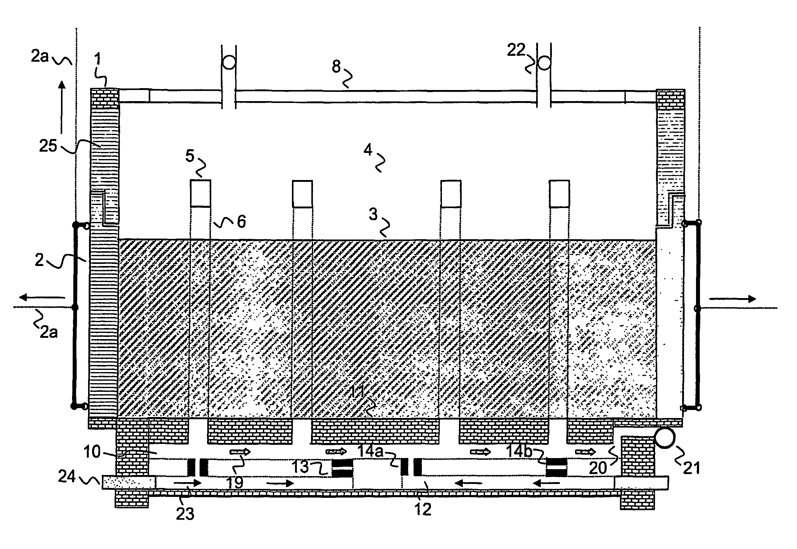
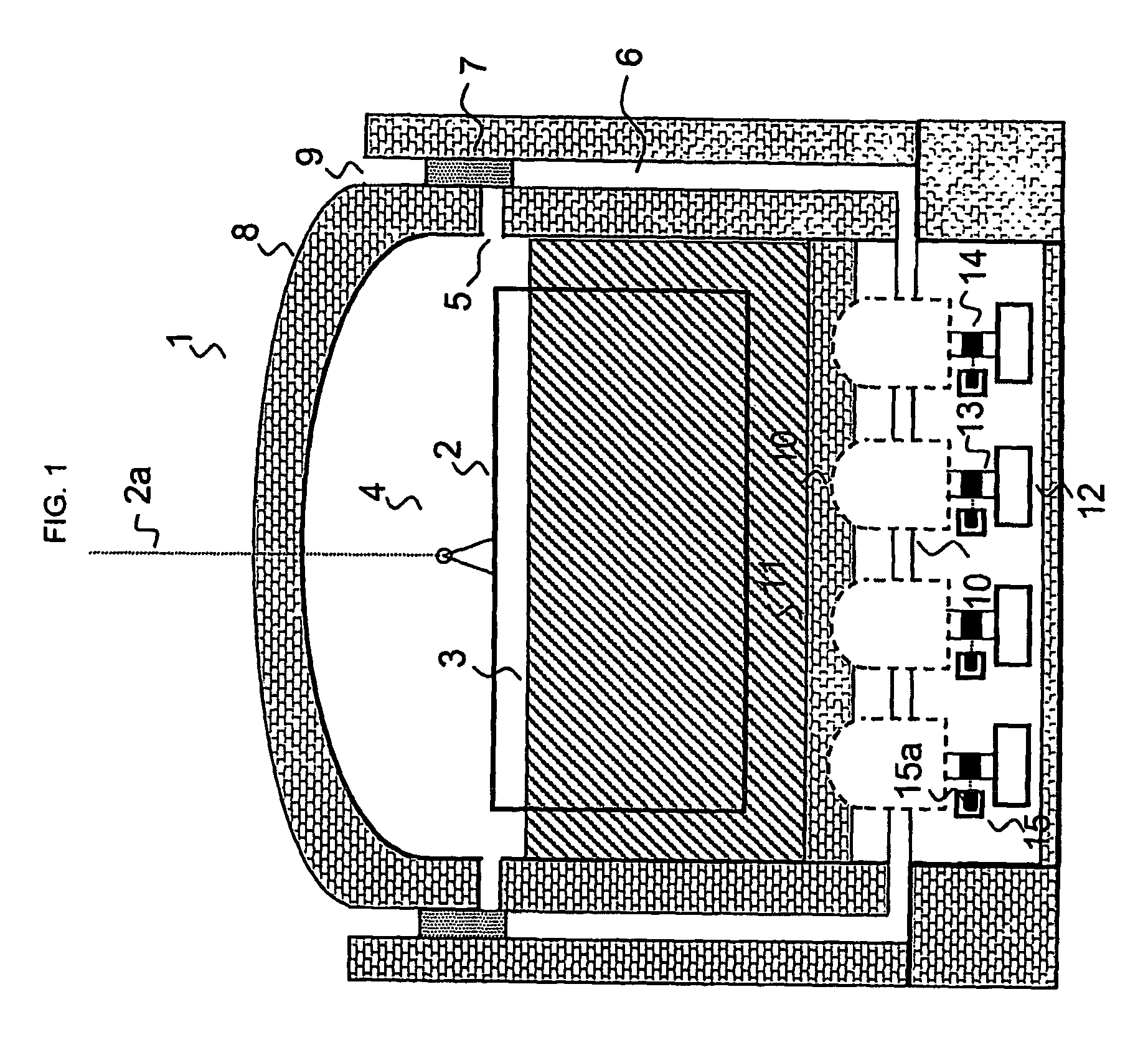
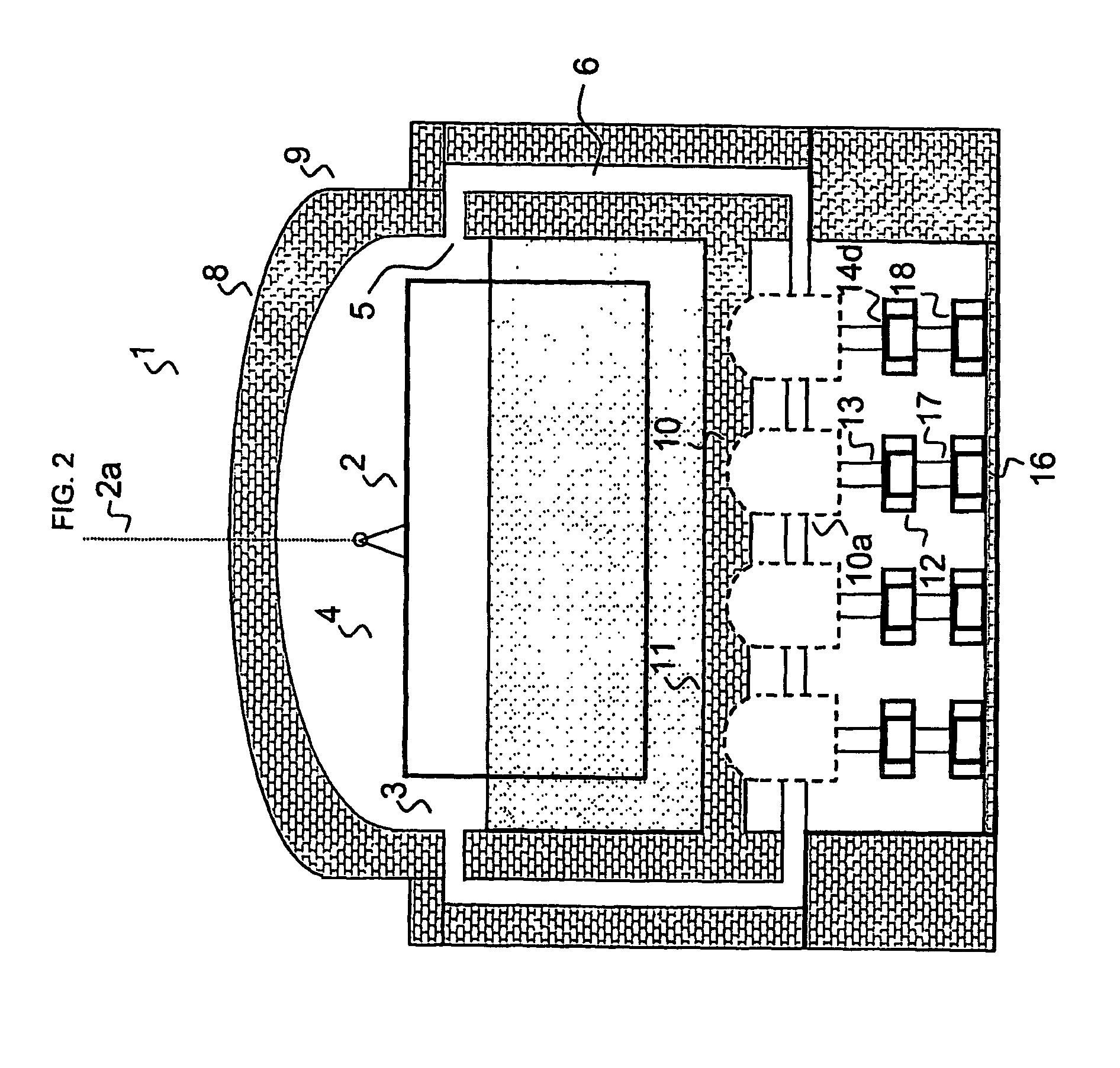
[0050]FIG. 1 shows a horizontal coke oven chamber (1), whose front-end opening is closed by the coke oven chamber door (2) with an opening mechanism (2a). The coke cake (3) below is indicatively shown. Located above the coke cake (3) is the oven free space (4). Coking gases may accumulate there. Through a lateral opening (5), the coking gases are conducted into the “downcomer” channels (6). It is possible to install a controlling facility (7) between the lateral opening (5) and the “downcomer” channels (6). Likewise, an opening (9) for supplying additional air may be located at the coke oven ceiling (8). The coking gases are conducted through the “downcomers” (6) and further on into the flue gas channels (10). The complete combustion of coking gases with secondary air occurs there. Located above the flue gas channels (10) is the coke cake (3), which is heated by combustion in the flue gas channels (10) through the coke oven chamber floor (11). The flue gas channels can be connected ...


PUM


Abstract

A device for feeding and controlling secondary air from secondary air ducts into flue gas channels of horizontal coke oven chambers is shown. The flue gas channels are located underneath the coke oven chamber floor on which coal carbonization is realized. The flue gas channels serve for combustion of partly burnt coking gases from the coke oven chamber. The partly burnt gases are burnt with secondary air, thus heating the coke cake also from below to ensure even coal carbonization. Secondary air comes from the secondary air ducts connected to atmospheric air and to the flue gas channels. Controlling elements are mounted in the connecting channels between the flue gas channels and secondary air ducts which can precisely control the air flow into the flue gas channels. Thereby, it is possible to achieve a much more regular heating and heat distribution in coke oven chambers. The actual controlling devices in the connecting channels can be formed by turnable pipe sections, wall bricks, or metal flaps. It is particularly advantageous to utilize a hump-like facility (tabouret) which sits in the secondary air ducts and which is comprised of a tabouret plate with a central opening that is slid under the corresponding embranchment to regulate the gas stream. The controlling mechanism can be actuated manually, electrically, or pneumatically. Thereby, the controlling device can also be automated.

Description

BACKGROUND[0001]The present invention relates to a device for improved feeding of secondary combustion air into the area of flue gas channels of horizontal coke oven chambers. Secondary combustion air is supplied into the flue gas channels from secondary air ducts which are usually installed under the flue gas channels. The present invention also relates to a device for controlling the feed volume of secondary air from the secondary air ducts into the area of flue gas channels. Owing to the improved supply and control of secondary air into the flue gas channels, the control of heat distribution and the combustion of coking gases in “Heat-Recovery” or “Non-Recoverycoke oven chambers can be improved.[0002]In most cases, coke oven chambers of the “Heat-Recovery” or “Non-Recovery” type are set-up in such a manner that coal carbonization is realized in a horizontally charged coke oven chamber which is sealed to air. During the carbonization of coal, coal by-products evolve which are ca...

Claims


Application Information

Patent Timeline
IPC IPC(8): C10B15/02C10B21/10C10B41/00
CPCC10B15/02C10B21/10C10B41/00
Inventor KIM, RONALDSCHUMACHER, RALF
Owner UHDE GMBH
Learn More