Cleaning module, EUV lithography device and method for the cleaning thereof

a technology of euv lithography and cleaning modules, which is applied in the direction of instruments, printers, therapy, etc., can solve the problems of increasing the required cleaning time, increasing the cleaning efficiency per cleaning cycle, and increasing the cleaning time, so as to achieve the effect of prolonging the service li

Inactive Publication Date: 2015-06-02
CARL ZEISS SMT GMBH
View PDF24 Cites 2 Cited by
  • Summary
  • Abstract
  • Description
  • Claims
  • Application Information

AI Technical Summary

Benefits of technology

[0006]It is an object of the present invention to improve the known cleaning heads such that a more gentle cleaning of the optical elements is enabled.
[0009]The element applying an electric and / or magnetic field, respectively the electromagnetic deflection unit, makes it possible to spatially deflect the produced atomic gas, preferably produced atomic hydrogen, insofar as it is in ionized form, or the ionized gas. The heating filament for the production of atomic gas, preferably atomic hydrogen, or the heating unit for the ionization of molecular gas, can thus be positioned such that there is no free line of sight (i.e. no unimpeded travel) between the heating filament or the heating unit on the one hand and a component to be cleaned or an area to be cleaned on the other. On the contrary, the hydrogen atoms present as ions or other ions are deflected by electric and / or magnetic fields to the site to be cleaned. The area to be cleaned is therefore no longer directly exposed to the thermal radiation of the heating filament or the heating unit or to contamination with material of the heating filament or the heating unit, this being a considerable advantage especially in the case of mirrors for the EUV or soft x-ray wavelength region. This is because such mirrors are often provided with heat-sensitive multilayer systems, which endow them with their optical capabilities. The temperature sensitivity of the multilayer coating of a mirror for the EUV or soft wavelength range limits the cleaning time and therefore the cleaning efficiency per cleaning cycle. The required cleaning time is thus increased and this reduces the production time. The cleaning efficiency with conventional cleaning modules is also reduced by the fact that the surface to be cleaned may be contaminated by material emerging from the filament or the heating unit during heating. As a result of the enabled gentle and at the same time target-orientated cleaning, the required cleaning time can be reduced, additional contamination can be avoided and the production time can thus be lengthened.
[0013]By the fact that the part of the atomic cleaning gas, preferably the atomic hydrogen, which is present in an ionized state, respectively that the ion share of a cleaning gas is deflected with an electric and / or magnetic field onto the component to be cleaned, it is possible to position the heating filament and the component to be cleaned with respect to one another in such a way that the component to be cleaned is not directly exposed to the thermal radiation of the heating filament, which leads to a longer service life of the component on account of the lower heat input.
[0014]It should be pointed out that, apart from ionized hydrogen, any charged particles, in particular other ionized cleaning gases, are suitable for the comparatively gentle and the target-orientated cleaning described here, especially ions of atoms or molecules, which react with the contamination to be removed to form volatile compounds, or of noble gases, which can clean the surface predominantly through a sputtering effect.

Problems solved by technology

The temperature sensitivity of the multilayer coating of a mirror for the EUV or soft wavelength range limits the cleaning time and therefore the cleaning efficiency per cleaning cycle.
The required cleaning time is thus increased and this reduces the production time.
The cleaning efficiency with conventional cleaning modules is also reduced by the fact that the surface to be cleaned may be contaminated by material emerging from the filament or the heating unit during heating.

Method used


Image

  • Cleaning module, EUV lithography device and method for the cleaning thereof
  • Cleaning module, EUV lithography device and method for the cleaning thereof
  • Cleaning module, EUV lithography device and method for the cleaning thereof

Examples


Embodiment Construction

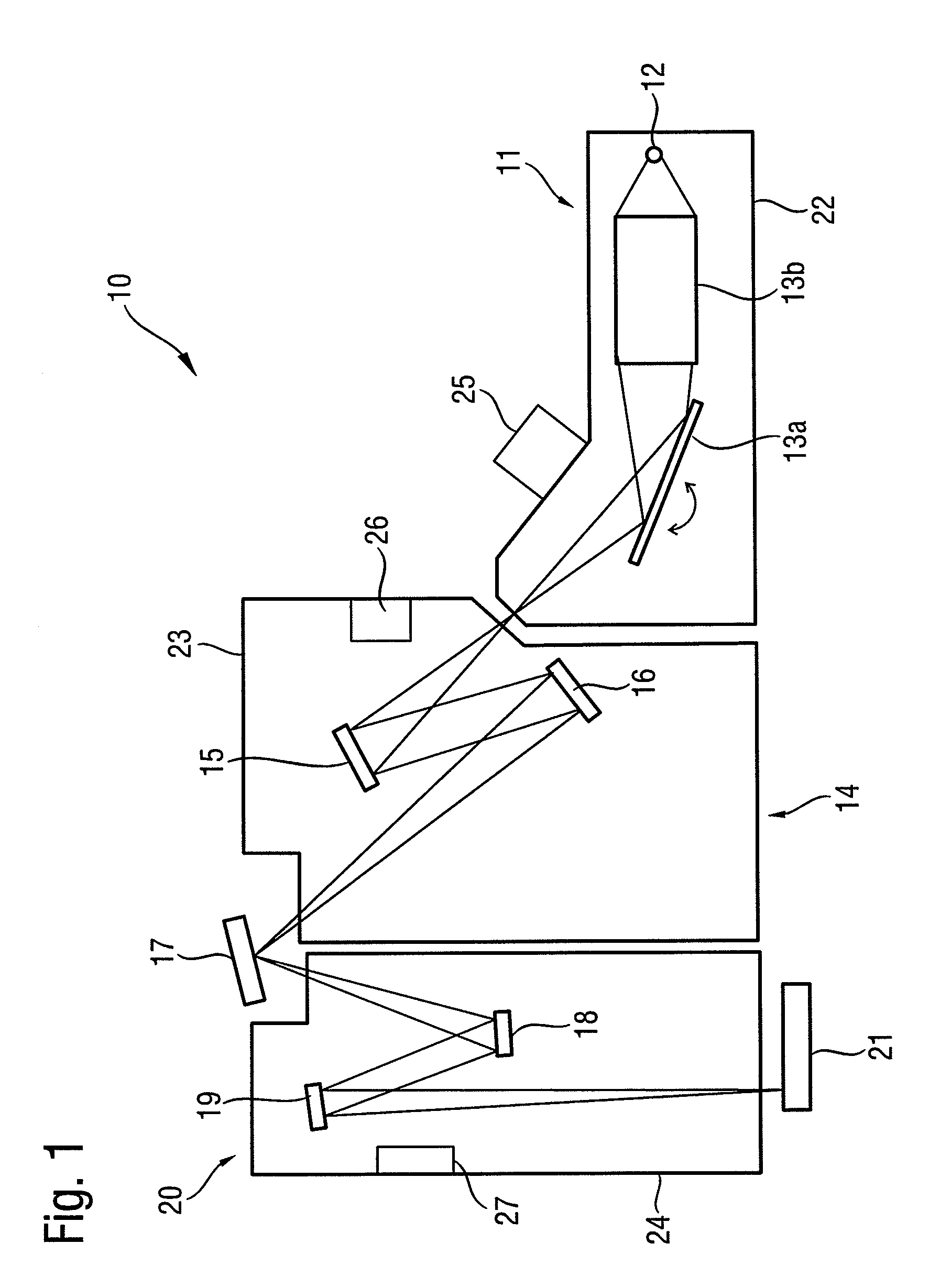
[0024]An EUV lithography device 10 is represented schematically in FIG. 1. Main components are a beam shaping system 11, an illumination system 14, a photomask 17 and a projection system 20. The EUV lithography device 10 is operated under vacuum conditions or in special atmospheres with a low partial pressure of a gas or a combination of gases, in order that the EUV radiation is absorbed or scattered as little as possible in its interior. In the present example, a pressure of approx. 10−4 mbar or less is complied with for this purpose, also with a special atmosphere.

[0025]A plasma source or also a synchrotron can for example be used as radiation source 12. The emerging radiation in the wavelength range from approx. 5 nm to 20 nm is first bundled in collimator 13b. Moreover, the desired operating wavelength can be filtered out with the aid of a monochromator 13a by varying the angle of incidence. In the stated wavelength range, collimator 13b and monochromator 13a are usually constit...


PUM

PropertyMeasurementUnit
angleaaaaaaaaaa
angleaaaaaaaaaa
angleaaaaaaaaaa

Abstract

In order to clean optical components (35) inside an EUV lithography device in a gentle manner, a cleaning module for an EUV lithography device includes a supply line for molecular hydrogen and a heating filament for producing atomic hydrogen and hydrogen ions for cleaning purposes. The cleaning module also has an element, (33) arranged to apply an electric and / or magnetic field, downstream of the heating filament (29) in the direction of flow of the hydrogen (31, 32). The element can be designed as a deflection unit, as a filter unit and / or as an acceleration unit for the ion beam (32).

Description

[0001]This is a Continuation of International Application PCT / EP2009 / 051330, with an international filing date of Feb. 5, 2009, which was published under PCT Article 21(2) in German, and the complete disclosure of which, including amendments, is incorporated into this application by reference.FIELD OF AND BACKGROUND OF THE INVENTION[0002]The present invention relates to a cleaning module for the cleaning of components of an EUV lithography device comprising a heating unit, and to a cleaning module for an EUV lithography device with a supply line for molecular hydrogen and a heating filament for producing atomic hydrogen for cleaning purposes, as well as to an EUV lithography device or a projection system or an illumination system for an EUV lithography device with such a cleaning module. Moreover, the present invention relates to methods for the cleaning of a component inside an EUV lithography device.[0003]In extreme-ultraviolet lithography devices, reflective optical elements for ...

Claims


Application Information

Patent Timeline
Patent Type & Authority Patents(United States)
IPC IPC(8): G03F7/20
CPCG03F7/70925
Inventor HEMBACHER, STEFANKRAUS, DIETEREHM, DIRK HEINRICHSCHMIDT, STEFAN-WOLFGANGKOEHLER, STEFANCZAP, ALMUTWIESNER, STEFANCHUNG, HIN YIU ANTHONY
Owner CARL ZEISS SMT GMBH
Why Eureka
Try Eureka