Method of production of electric resistance welded steel pipe and high Si or high Cr electric resistance welded steel pipe

a technology of electric resistance welded steel pipe, which is applied in the direction of manufacturing tools, machines/engines, transportation and packaging, etc., can solve the problems of air entanglement, insufficient reduction of oxygen concentration in plasma jets, and inability to stably reduce the amount of oxides of weld zones, etc., to achieve stably, high si, high cr electric resistance

Inactive Publication Date: 2015-06-09
NIPPON STEEL CORP
View PDF12 Cites 6 Cited by
  • Summary
  • Abstract
  • Description
  • Claims
  • Application Information

AI Technical Summary

Benefits of technology

[0009]Therefore, the present invention was made in consideration of the above problem points and has as its object the provision of a method of production of electric resistance welded steel enabling the occurrence of weld defects due to oxides to be stably reduced and furthermore enabling the plasma jet noise occurring at the time of welding to be reduced and the provision of high Si or high Cr electric resistance welded steel pipe.

Problems solved by technology

However, the method of production of electric resistance welded steel pipe described in the above-mentioned Japanese Patent Publication (A) No. 2006-026691 uses a turbulent plasma jet (plasma fired from plasma gun), so there was the problem that even if arranging a shield gas around it for blocking the air, the air would end up being entrained.
For example, even if using the firing angle and flow rate of shield gas proposed in Japanese Patent Publication (A) No. 2004-243374, the concentration of oxygen in the plasma jet sometimes could not be sufficiently reduced.
For this reason, with the method of production of electric resistance welded steel pipe described in Japanese Patent Publication (A) No. 2006-026691, sometimes the amount of oxides of the weld zone cannot be stably reduced and the number of defects ends up exceeding the target value.
Furthermore, the method of production of electric resistance welded steel pipe described in Japanese Patent Publication (A) No. 2006-026691 uses a turbulent, high speed plasma jet, so there is also the problem of a large plasma jet noise being caused when welding abutting parts.

Method used


Image

  • Method of production of electric resistance welded steel pipe and high Si or high Cr electric resistance welded steel pipe
  • Method of production of electric resistance welded steel pipe and high Si or high Cr electric resistance welded steel pipe
  • Method of production of electric resistance welded steel pipe and high Si or high Cr electric resistance welded steel pipe

Examples


example 1

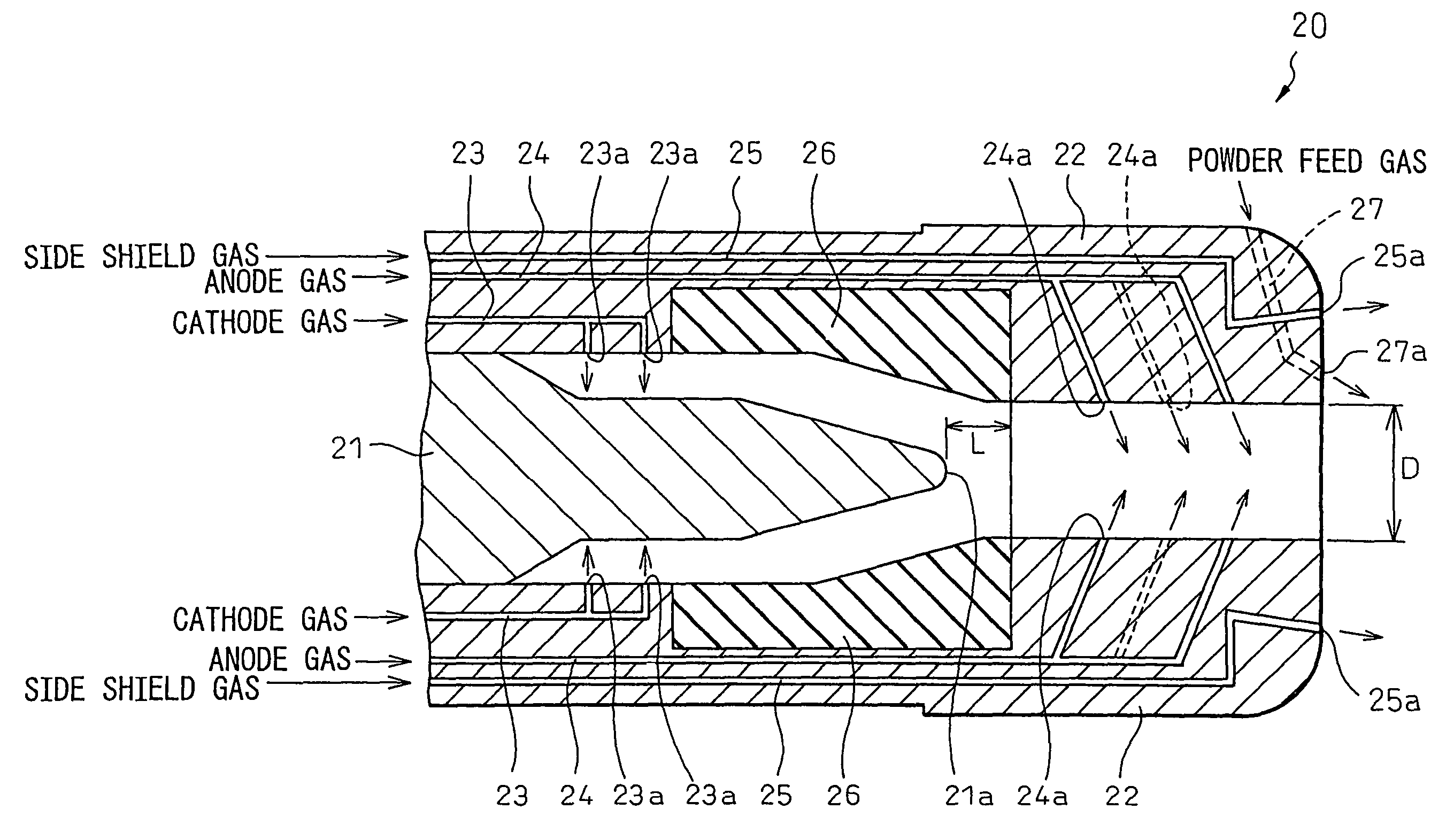
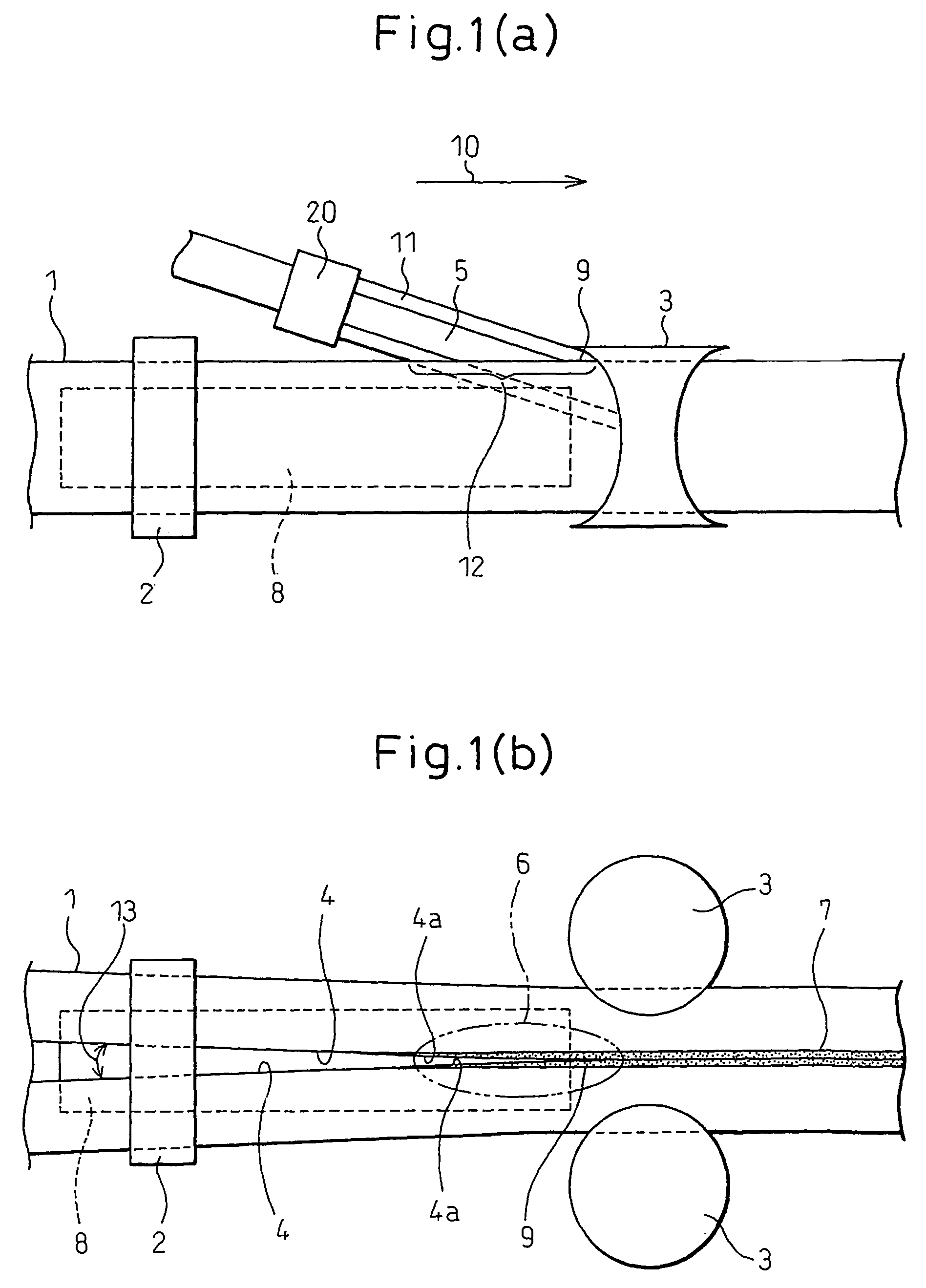
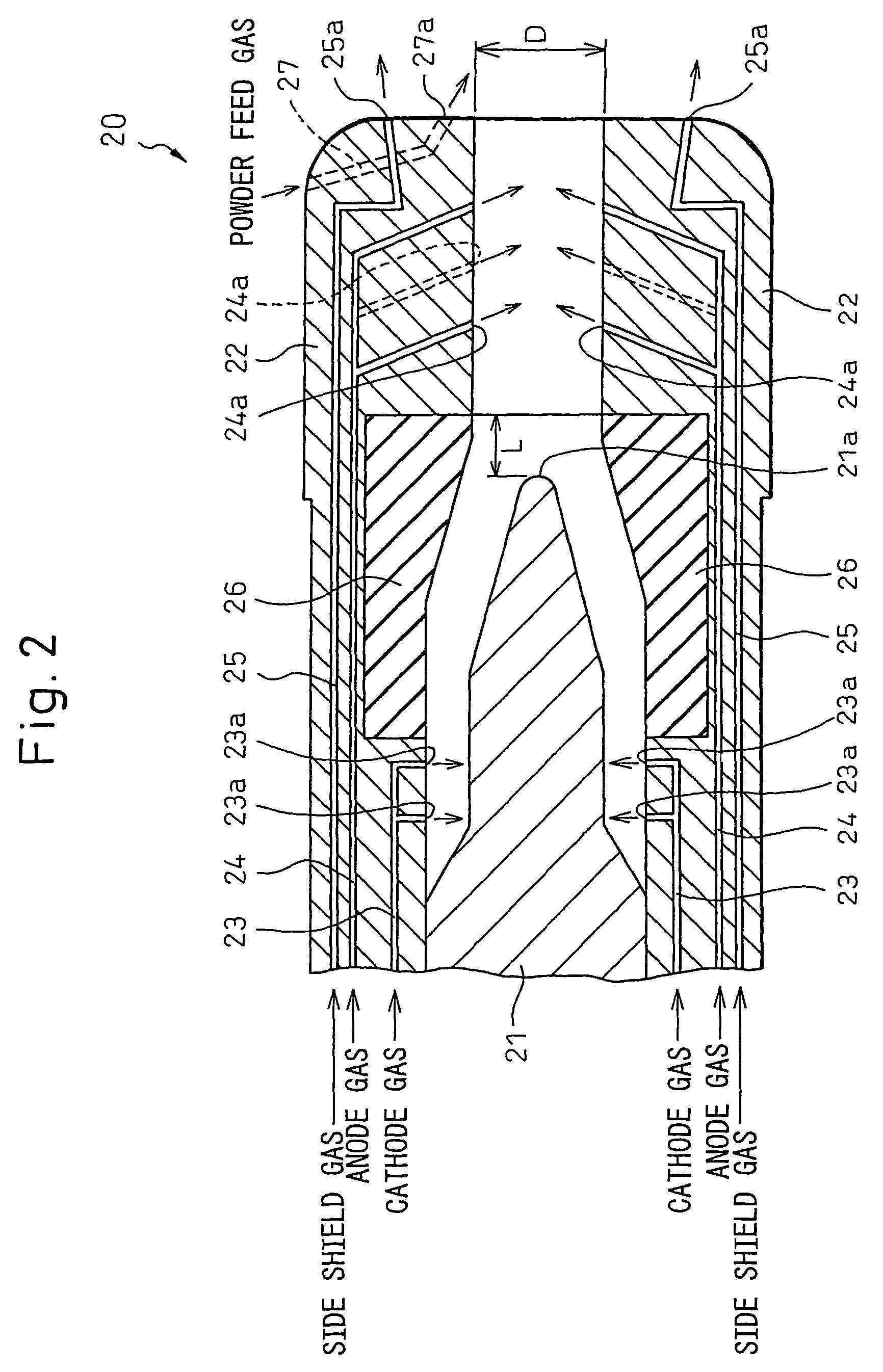
[0071]Below, examples of the present invention and comparative examples outside the range of the present invention will be given to specifically explain the effects of the present invention. In the present example, steel plate having the steel ingredients of Table 1 and a plate thickness of 5.3 mm, 11 mm, or 19 mm was used and a reducing plasma working gas of a mixed gas of H2 gas, Ar gas, and nitrogen gas was used to produce electric resistance welded steel pipe by the method shown in the above-mentioned FIG. 1 and investigate the rate of occurrence of weld defects in the weld zone and the magnitude of the plasma jet noise at the time of welding.

[0072]The electric resistance welding conditions at that time, at the time of a plate thickness of 5.3 mm, were made a weld rate of 33 m / min, a weld input of 570 kW, a power feed distance (distance from high frequency coil 2 to weld point 9) of 160 mm, an upset amount of 3 mm, and an average apex angle (notation 13 in FIG. 1(b)) of 4°. Furt...

example 2

[0088]Next, examples of electric resistance welded steel pipe according to the resent invention and comparative examples outside the range of the present invention will be given to specifically explain the effects of the present invention. In the present example, a hoop material having the steel ingredients shown in Table 4, a plate thickness of 6.0 mm, and a width of 32 mm obtained by laboratory melting and laboratory rolling was used and a mixed gas of H2 gas and Ar gas was used as a reducing plasma working gas to prepare a electric resistance welding test piece by a laboratory welder and investigate the rate of occurrence of weld defects of that weld zone (water spraying rate of 1 l / min).

[0089]The electric resistance welding conditions at that time were made a welding rate of 33 m / min, a weld input of 320 kW, a power feed distance of 150 mm, an upset amount of 6 mm, and an average apex angle of 4°. For the anode inside diameter, Ar gas and H2 gas flow rates, value of {4×(ΣGiMi)} / ...

example 3

[0095]Next, examples in the case of changing the impede case material when producing steel pipe by the present invention and comparative examples outside the range of the present invention will be given to specifically explain the effects of the present invention. In the present example, damage to the impeder case when producing electric resistance welded steel pipe using steel plate with a plate thickness of 5.3 mm and a width of 273 mm (D of Table 1) and using as the reducing plasma working gas, a mixed gas of H2 gas and Ar gas was investigated. For the anode inside diameter, Ar gas and H2 gas flow rates, the value of {4×(ΣGiMi)} / {π×D×μave,T=7000}, current, and voltage, the conditions of Invention Example 1 in Table 2 and Table 3 were used. The results are shown in Table 5. Note that as an overall evaluation, passing was indicated as “◯” while failing was indicated as “χ”.

[0096]

TABLE 5MeltCracking due to thermalElectricalDamage due toMaterialdamageshockresistance (Ω cm)eddy curren...


PUM

PropertyMeasurementUnit
temperatureaaaaaaaaaa
diameteraaaaaaaaaa
voltageaaaaaaaaaa

Abstract

The present invention provides a method of production of electric resistance welded steel pipe able to stably reduce weld defects due to oxides by firing plasma and furthermore able to reduce plasma jet noise and comprises shaping steel plate 1 into a tube and electric resistance welding the abutting end faces 4 during which blowing on at least the abutting end faces 4a in the region 6 at the welding upstream side from the weld point 9 where the temperature becomes 650° C. or more a reducing high temperature (pseudo) laminar plasma obtained by applying voltage to a reducing gas containing H2 gas: 2 to 50 vol % to which is added a balance of Ar gas alone or a mixed gas of Ar gas to which N2 gas, He gas, or both are added. At that time, it is preferable to make the applied voltage over 120V and the make the plasma blowing conditions satisfy the following formula (1).150<4×(∑Gi⁢Mi)π×D×μava,T=7000<400<1>

Description

[0001]This application is a national stage application of International Application No. PCT / JP2008 / 054100, filed 29 Feb. 2008, which claims priority to Japanese Application No. 2007-052423, filed 2 Mar. 2007, which is incorporated by reference in its entirety.TECHNICAL FIELD[0002]The present invention relates to a method of production of electric resistance welded steel pipe used mainly for oil or natural gas line pipes, oil well pipes, and steel pipes for nuclear power use, geothermal use, chemical plant use, mechanical structure use, and general piping use, more particularly relates to a method of production of electric resistance welded steel pipe suitable when using steel plate containing large amounts of Cr, Si, and other elements easily forming oxides as the steel pipe material and to a high Si or high Cr electric resistance welded steel pipe.BACKGROUND ART[0003]FIG. 4 is a schematic view showing a conventional method of production of electric resistance welded steel pipe. As ...

Claims


Application Information

Patent Timeline
Patent Type & Authority Patents(United States)
IPC IPC(8): B23K10/00B23K13/00B23K13/06
CPCB23K13/00B23K10/00B23K13/06Y10T428/12292B23K2201/06B23K2203/04B23K11/0873B23K11/16B23K11/34B23K11/36B23K28/02B23K2101/10B23K2101/18B23K2101/06B23K2103/04B21C37/08H05H1/34
Inventor HAMATANI, HIDEKIKODAMA, SHINJIMIZUHASHI, NOBUOTAKEUCHI, SUNAONAKAJI, TOMOHIROMIYAKAWA, TAKASHIASAHI, HITOSHITANIMOTO, MICHITOSHIMUKAI, MICHIMASA
Owner NIPPON STEEL CORP
Why Eureka
Try Eureka