Method and apparatus for photomagnetic imaging

a photomagnetic imaging and apparatus technology, applied in the field of photomagnetic imaging, can solve the problems of multi-modality approaches, cumbersome and complex interfaces, and significant barriers, and achieve the effects of eliminating image artifacts, improving localization and resolution of resulting images, and reducing the number of modalities

Active Publication Date: 2015-07-14
RGT UNIV OF CALIFORNIA
View PDF15 Cites 2 Cited by
  • Summary
  • Abstract
  • Description
  • Claims
  • Application Information

AI Technical Summary

Benefits of technology

[0016]PMI's principal advantage over other methods of optical imaging is that it can detect the same tissue properties as in DOT or photoacoustic imaging, but operates at the resolution of an MRI machine. This results in significantly better localization and resolution of the resulting images than in DOT, without the requirement for tissue contact as in PAT or PAM. Furthermore, PMI does not have the same acoustic problems resulting from the scattering of waves through acoustically heterogeneous tissues as seen in photoacoustic imaging techniques, allowing PMI to image deeper than PAT. Finally, because PMI measures the entire volume of the tissue using magnetic imaging thermometry, the technology is not limited to external measurements. This eliminates the need to assume tissues are homogeneous and eliminates image artifacts due to unwanted reflections of sound waves. Furthermore, because measurement of PMI uses an MRI machine, it does not require tissue contact or external fiber bundles, and measurements can instead be taken when using catheter-based illumination fibers. These illumination fibers can be used to deliver continuous wave (CW) laser light into tissues not readily accessible externally, allowing for potential imaging applications in many internal parts of the body.
[0017]The proposed PMI system can be implemented as a low-cost add on to the currently available MR systems due to utilization of cheaper continuous wave lasers as well as absence of an optical detection system. The implementation of the PMI on current MRI coils is simple and convenient. Cumbersome and complex interfaces present significant barriers for many other kinds of multi-modality approaches. MRI is currently the standard modality for clinical management for breast cancer. Hence, PMI will impact breast cancer management whenever MRI is used from diagnosis to therapy monitoring. For instance, a light pain-free compression (5 cm-6 cm) PMI breast imaging system can be designed with illumination from both sides. The combination of MRI & PMI may not only impact clinical success, but also speed up development of optical molecular probes by providing accurate distribution of molecular optical probes in breast. Furthermore, PMI can be translated for lymph node imaging for which the high resolution capability is important to see the nodes deep in the tissue. Finally, catheter based PMI might find interesting applications besides breast cancer in the future. For example, a tiny illumination fiber may be used to deliver the light into the tissue for one-shot PMI illumination. Potential catheter based PMI applications may include: prostate imaging via a urethral probe, interrogating prostate tissue to help MR guided HIFU therapy for prostate cancer, and pancreas imaging due to its thin structure.

Problems solved by technology

Cumbersome and complex interfaces present significant barriers for many other kinds of multi-modality approaches.

Method used


Image

  • Method and apparatus for photomagnetic imaging
  • Method and apparatus for photomagnetic imaging
  • Method and apparatus for photomagnetic imaging

Examples


example 1

Phantom Studies

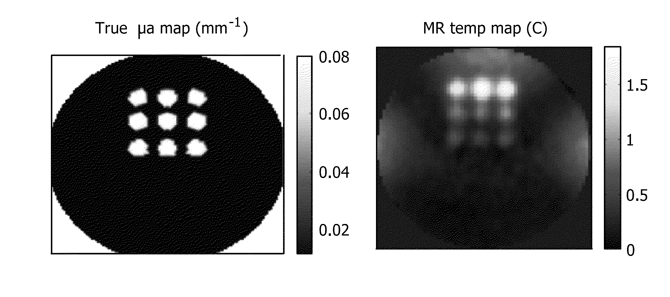
[0069]Phantom studies mimicking small animals may be undertaken. An agar based gelatin phantom is used for this purpose. The absorption and reduced scattering coefficients of the phantom are 0.01 mm−1 and 1 mm−1, respectively. A solid state laser emitting at 808 nm is used for illumination. Its output is coupled to three 20 m long multimode fibers of 1 mm in diameter, using a custom made fiber optic connector. The other end of the fibers is polished and fixed into a 3″ long plastic probe. The laser diode controller and the laser itself is kept in an MRI control room, and the optical fiber is passed through waveguides into the MR scanner room. An animal MR / Optical imaging interface for conventional optical tomography studies is employed. The agar phantom is placed in an RF coil that is fixed in the center of the fiber interface, and the fiber probes inserted through the top and two side holes (perpendicular to the top one) on the fiber optic interface. The light output...

example 2

Rat Imaging

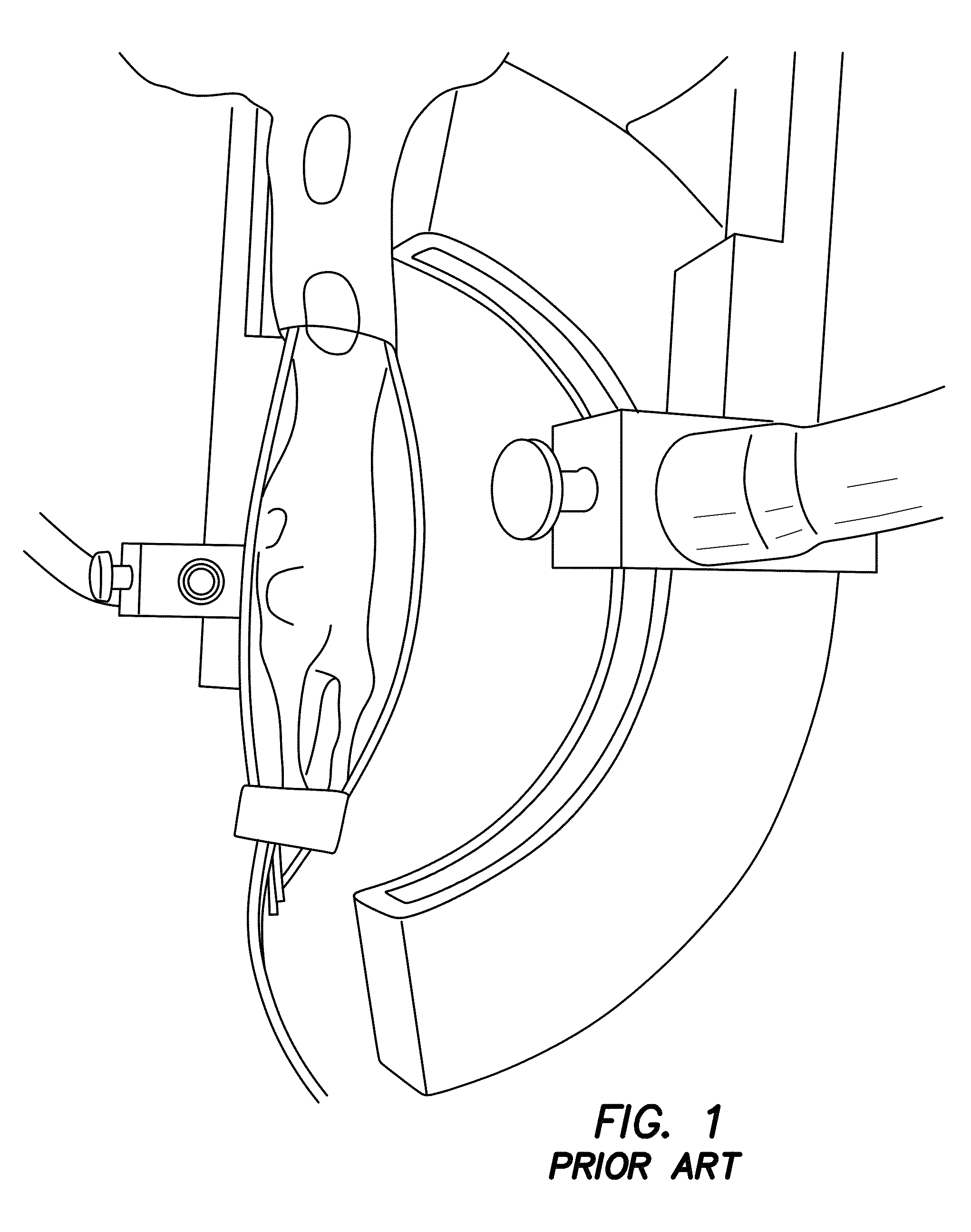
[0070]The utility of PMI in vivo is demonstrated by rat imaging with an RF coil using the experimental prior art photoacoustic tomography setup in FIG. 1. Data is acquired using a single illumination probe on top. Temperature images is acquired from a rat. As seen from FIGS. 7a-7e, data acquired from this embodiment shows that we can successfully heat the animal tissue up to 1.5 cm depth within ANSI limit. What is shown are in vivo results using a rat. These four temperature maps were obtained while the laser is on and under ANSI limit. The images of FIGS. 7d and 7e show the superimposition of anatomic image and temperature map obtained at 88s. The yellow arrow shows the probing depth, which is 1.5 cm. The red arrows indicates the illumination area. Hence, PMI is achieved for whole-body imaging of rats using illumination from multiple views. It is expected to probe much deeper in other tissues such as breast due to its lower optical absorption compared to animal tissue.

example 3

Multiple Fiber Illumination

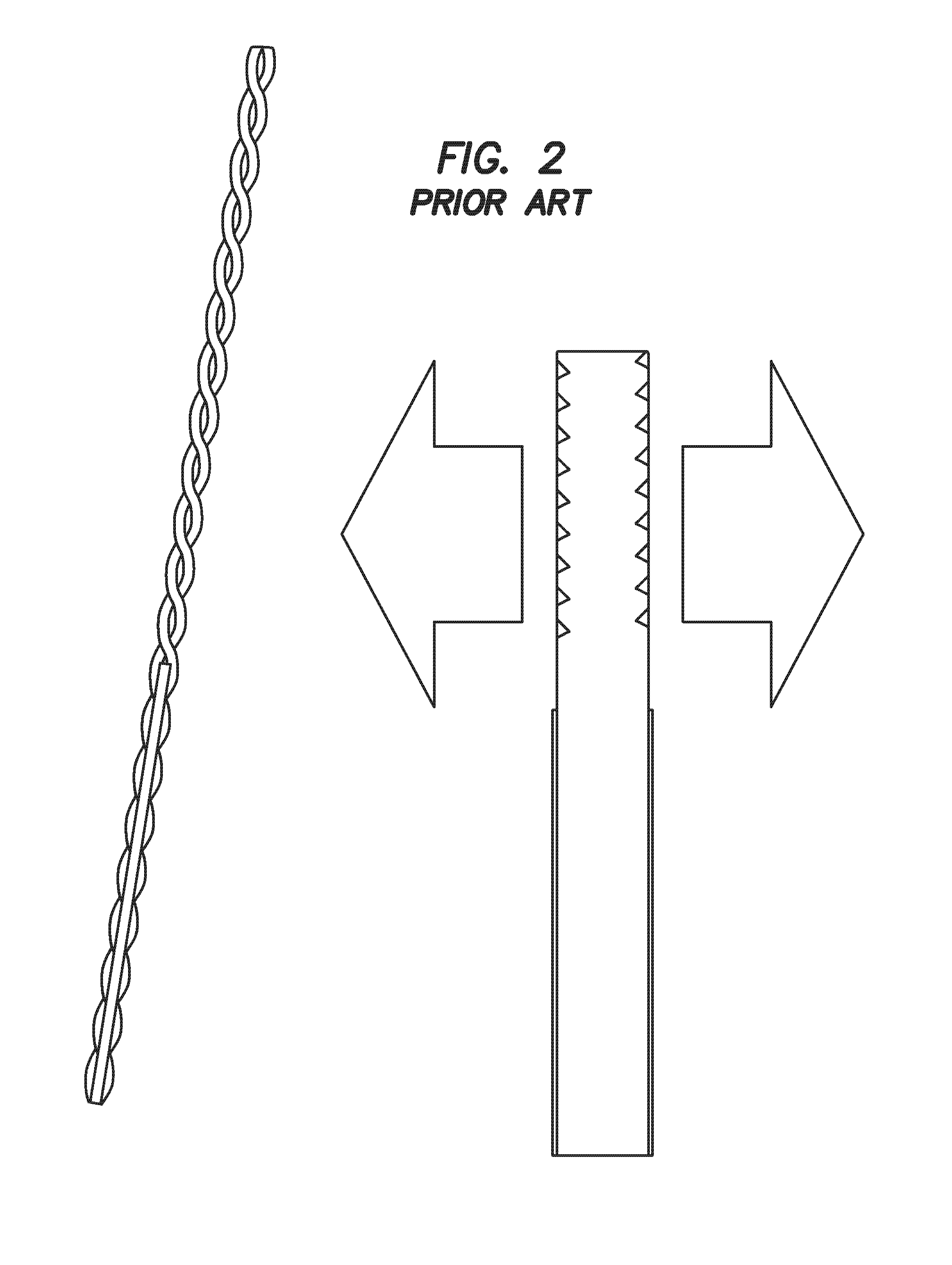
[0071]In a further embodiment, multiple side-shooting threaded diffuser fibers are distributed inside the RF-coil around the sampling volume. FIG. 2 is a diagram of a conventional threaded diffuser tip available from Polymicro Technologies, Phoenix, Ariz., which is suitable for a catheter-based PMI approach simultaneously illuminating all surrounding tissue. This embodiment is used to implement illumination patterns within smaller volume scanners. The diffuser fibers are customized to illuminate only a half cylindrical area instead of a full cylindrical area.


PUM


Abstract

A method for photomagnetic imaging of tissue includes the steps of heating the tissue using light; measuring a change in temperature of the tissue with magnetic resonance thermometry; and creating an optical property map from the measured change in temperature. An apparatus for performing photomagnetic imaging of tissue which includes a light source to heat the tissue, a magnetic resonance imaging system to measure a change in temperature of the tissue, and a data processor to generate an optical property map from the measured change in temperature. An optical property map of tissue photomagnetic imaging of tissue produced by: heating the tissue using light; measuring a change in temperature of the tissue with magnetic resonance thermometry; and creating an optical property map from the measured change in temperature.

Description

[0001]The present application is related to U.S. Provisional Patent Application Ser. No. 61 / 550,258, filed on Oct. 21, 2012, which is incorporated herein by reference and to which priority is claimed pursuant to 35 USC 119.BACKGROUND[0002]1. Field of the Technology[0003]The disclosure relates to the field of imaging, particularly photomagnetic imaging using laser heating and magnetic resonance imaging.[0004]2. Description of the Prior Art[0005]Over the last few decades, a variety of in vivo imaging techniques have been developed using a broad spectrum of technologies to obtain structural, functional, and molecular information about the tissue under investigation. One category of these techniques is optical imaging. Optical imaging works by shining laser light on tissue and then measuring the results. Optical imaging can provide functional information, such as hemoglobin concentration, and can visualize exogenous contrast agents as well as molecular and functional markers. In vivo op...

Claims


Application Information

Patent Timeline
Patent Type & Authority Patents(United States)
IPC IPC(8): A61B5/055A61B5/01A61B5/00G01R33/48
CPCA61B5/055A61B5/0093A61B5/01G01R33/4804
Inventor GULSEN, GULTEKINTHAYER, DAVIDLIN, YUTINGUNLU, MEHMET BURCIN
Owner RGT UNIV OF CALIFORNIA
Why Eureka
Try Eureka