Circular antenna array for vehicular direction finding

a circular antenna array and vehicular direction technology, applied in the field of radio direction finding antennas, can solve the problems of not being able to specifically design directions, consuming too much power, and bulky systems,

Inactive Publication Date: 2015-07-14
KING FAHD UNIVERSITY OF PETROLEUM AND MINERALS
View PDF18 Cites 221 Cited by
  • Summary
  • Abstract
  • Description
  • Claims
  • Application Information

AI Technical Summary

Problems solved by technology

These systems were bulky and consumed too much power, and in some cases, were impractical due to mobility related issues.
Several antenna array designs exist, but none appear to have actually been designed specifically for direction finding with vehicle localization as its application.

Method used


Image

  • Circular antenna array for vehicular direction finding
  • Circular antenna array for vehicular direction finding
  • Circular antenna array for vehicular direction finding

Examples


Embodiment Construction

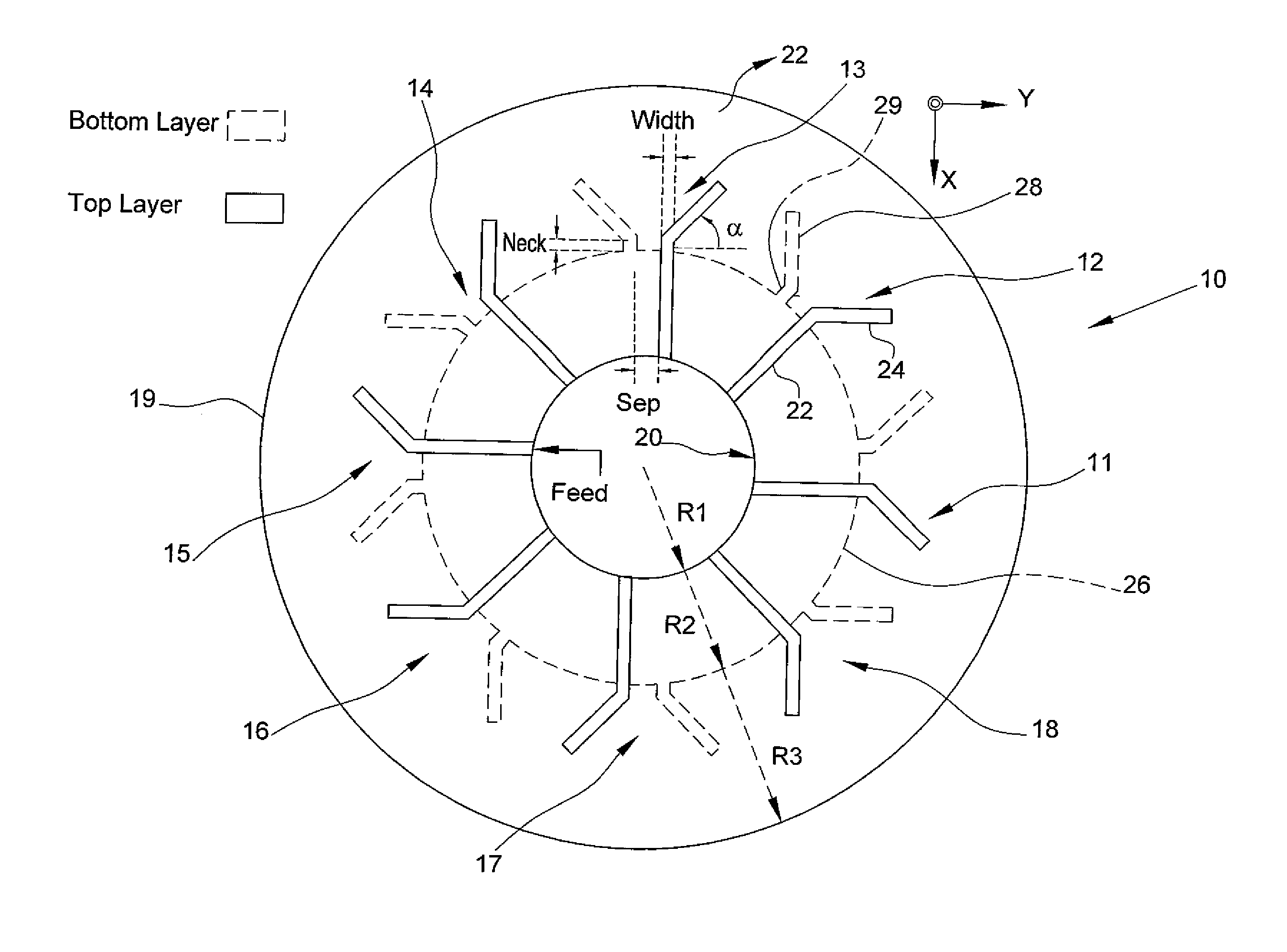
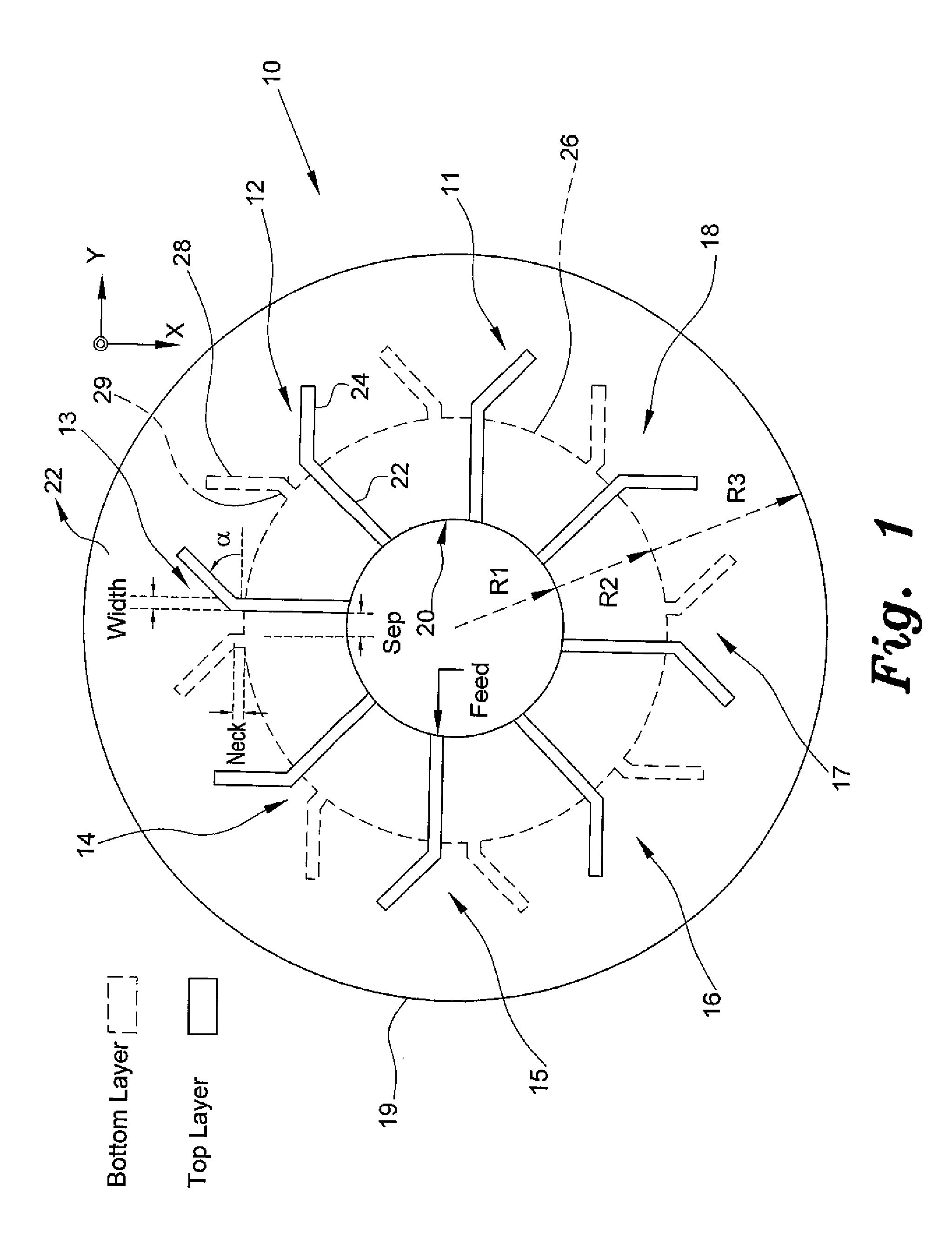
[0026]The circular antenna array for vehicular direction finding, a first embodiment of which is generally referred to by the reference number 10, provides a compact antenna array that blends well into the aesthetics of a vehicle and facilitates location of the vehicle with minimal effort. As shown in FIG. 1, the circular antenna array 10 includes a circular disc 19 constructed from non-conducting dielectric material, such as a printed circuit board (PCB), silica, and the like, with a given ∈r (dielectric constant). In this embodiment, the ∈r for the disc 19 is about 3.8, and the dimensions of the disc 19 are about 200 mm in diameter (radius R3 of 100 mm) and 0.8 mm in thickness.

[0027]A plurality of V-shaped microstrip antennas 11-18 have been formed on opposite sides of the disc 19. The antennas are radially spaced at equal angles about the disc 19. On the top side or layer, each V-shaped antenna 11-18 includes a top leg element 22 extending radially from a center hole 20 that pref...


PUM


Abstract

The circular antenna array for vehicular direction finding applications is a circular disc having a plurality of microstrip antennas radially spaced around the disc at equal angles. In one embodiment, the circular antenna array includes V-shaped antennas, and in another embodiment, the antennas are Yagi antennas. The circular antenna array can operate under two modes, switched and phased, in the 2.45 GHz band with an operating bandwidth of at least 100 MHz. The circular antenna array is configured to be installed in vehicles. Selective transmittal of an RF signal from a key fob generates a response signal from a specific antenna element receiving the RF signal in line with the direction of origin thereof. An LED panel indicates proximity and direction to the vehicle being located.

Description

BACKGROUND OF THE INVENTION[0001]1. Field of the Invention[0002]The present invention relates to radio direction finding antennas, and particularly to a circular antenna array for vehicular direction finding.[0003]2. Description of the Related Art[0004]Wireless technology, such as radio frequency (RF) and direction finding (DF) systems, have been popular with the military since their first use in World War II. Traditionally these systems were used in war zones to detect the presence of unwanted transmitters, a term commonly referred to in the military as “fox hunting”. This process involved rotating a directional antenna across the 360° azimuth plane to find the most probable direction of unwanted transmission. If the “fox” transmitted for long enough, its position could be located quite accurately. More recently, direction finding has been utilized in civilian applications including disaster recovery, wildlife tracking and locating illegal transmitters in licensed frequency bands. ...

Claims


Application Information

Patent Timeline
Patent Type & Authority Patents(United States)
IPC IPC(8): G08G1/123H01Q19/24H01Q9/28H01Q1/36H01Q9/04H01Q9/16G05B11/01H01Q21/20H01Q9/26
CPCG08G1/123H01Q9/16H01Q19/24H01Q21/205H01Q9/44
Inventor SHARAWI, MOHAMMAD S.KHAN, FAROOQ SULTAN SULTANALOI, DANIEL N.
Owner KING FAHD UNIVERSITY OF PETROLEUM AND MINERALS
Why Eureka
Try Eureka