
Apparatus and method for the deposition of biological material in a target substrate

a biological material and target substrate technology, applied in the field of apparatus and method for the deposition of biological material in a target substrate, can solve the problems of insufficient development of the targeted and reproducible deposition of cells or cell components in biological materials, high mechanical stress on suspended cells, and insufficient degree of development of the targeted and reproducible deposition technique, etc., to achieve the effect of improving the functional reliability of the deposition apparatus, improving accuracy and reproducibility

Active Publication Date: 2015-08-18
FRAUNHOFER GESELLSCHAFT ZUR FOERDERUNG DER ANGEWANDTEN FORSCHUNG EV
View PDF15 Cites 17 Cited by
  • Summary
  • Abstract
  • Description
  • Claims
  • Application Information

AI Technical Summary

Benefits of technology

The invention is a method and apparatus for depositing biological material onto a target substrate with high accuracy and speed. The apparatus can be moved relative to the substrate to embed the material in a larger target. It can also include an imaging device to capture images and control the deposition, a navigation device to increase accuracy, and a conditioning device to set desired conditions on the substrate. The invention allows for the deposition of large amounts of biological material in a target substrate and can be used for in vitro applications.

Problems solved by technology

While numerous techniques (e.g. dispensing techniques, picking / spotting techniques, etc.) are available for depositing biological cells on solid substrate surfaces, the technique concerning the targeted and reproducible deposition of cells or cell components in biological material has been developed only to an insufficient extent.
The injection of cells into tissue, e.g. heart muscle tissue, has the disadvantage that, during the injection, the dense material of the tissue has to be displaced, with the suspended cells being subjected to high mechanical stress.
Furthermore, it is disadvantageous that usually considerable volumes of liquid are introduced into the tissue during the injection, which are undesirable or cause injury to the tissue.
Finally, the injection results in undefined depositions, since the distribution of the cells in the tissue can barely be influenced.
Injecting the cells into the bloodstream does allow a gentle transfer into the organism; however, the problem of geometrically undefined deposition increases still further.
In the bloodstream, a drifting of the cells into parts of the organism outside the target tissue may lead to undesired side effects, which may even go as far as tumor formation.
In the case of injecting stem cells or precursor cells into a cell culture or a biological organism, there are additional requirements which are met only insufficiently by conventional methods.
This technique may be disadvantageous in practice if large numbers of cells are to be transferred.
Since the positioning of the transfer tool is extremely time-consuming, the technique described in WO 2004 / 074426 may be unsuitable for a routine deposition of such large numbers of cells.
A transport or deposition of larger cells or of whole cell groups is thus not possible.
The abovementioned problems occur not only in the deposition of stem cells, but rather also during the introduction of other cell types, cell components or active substances when a gentle transfer without losses under predefinable geometric or quantitative conditions is necessary.
By way of example, the targeted deposition of active substances, such as for example differentiation factors or growth factors, in tissue is a problem that has not yet been solved.
Furthermore, said problems occur not only during the deposition of biological material in an organism, but rather also during the embedding of biological material in biological or non-biological substrate materials outside an organism, such as for example in a cell culture.

Method used


Image

  • Apparatus and method for the deposition of biological material in a target substrate
  • Apparatus and method for the deposition of biological material in a target substrate
  • Apparatus and method for the deposition of biological material in a target substrate

Examples


Embodiment Construction

[0059]The invention will be described below firstly with reference by way of example to the embedding of biological cells in a biological tissue inside or outside a biological organism. However, the invention is not restricted to this application. The embedding of biological materials in the volume or surface of other target substrates, such as for example cell cultures, can be carried out in a corresponding manner. Details regarding the transformation of biological materials into the frozen state, such as for example details concerning the cooling medium used, the addition of a cryoprotectant or the steps of the freezing method, will not be explained below since they are known per se from the conventional cryopreservation of biological samples.

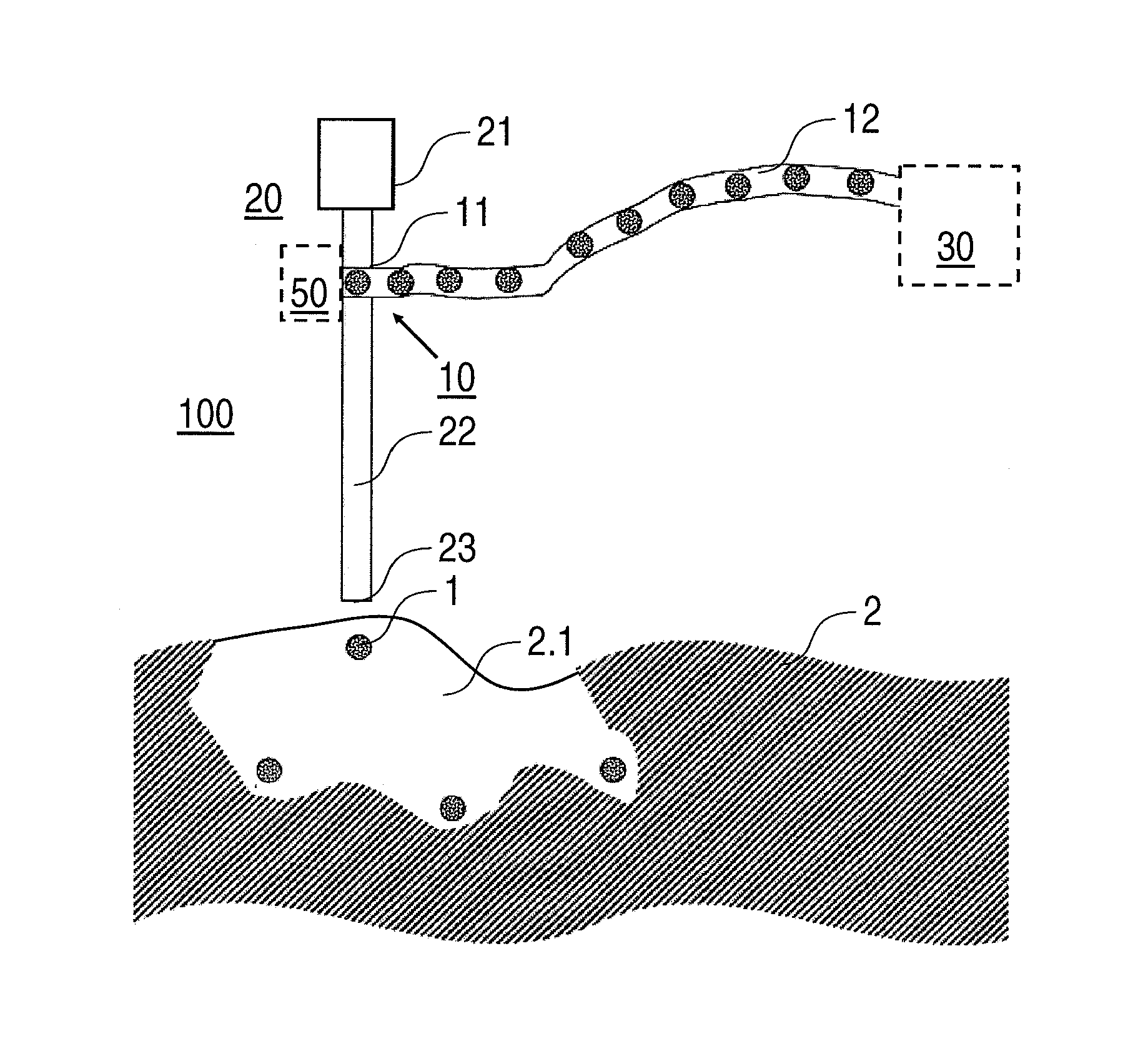
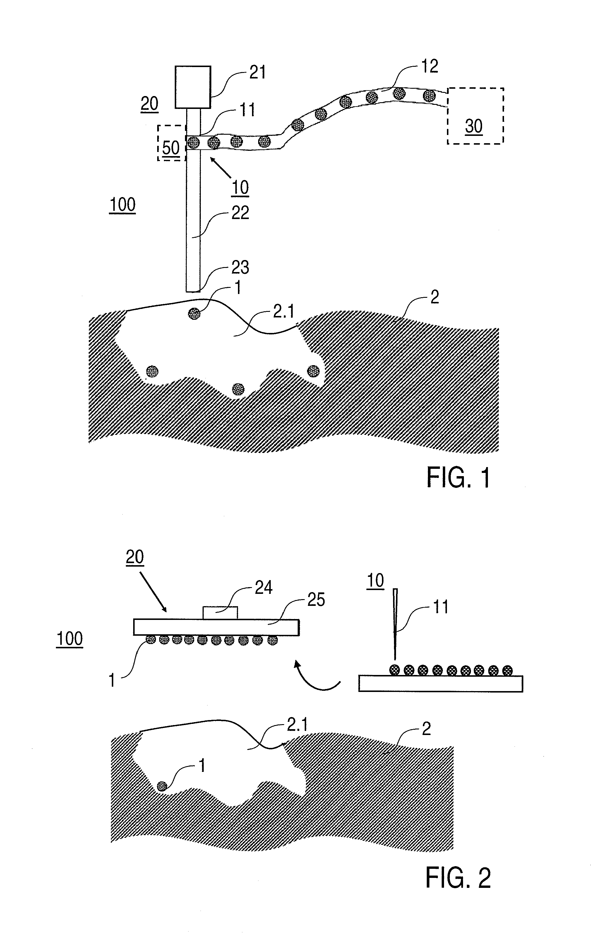
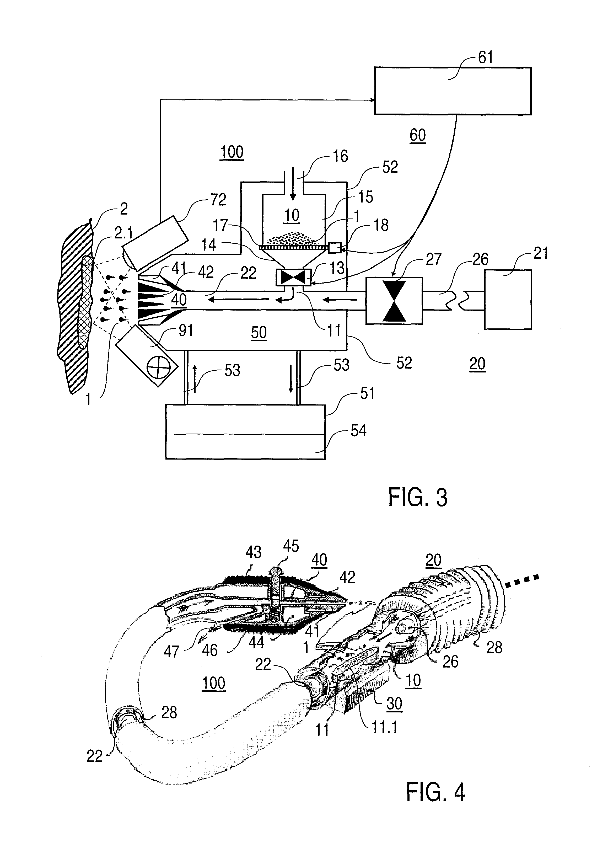
[0060]FIG. 1 shows a first embodiment of a deposition apparatus 100 according to the invention in a schematic sectional view. The deposition apparatus 100 comprises a charging device 10 with a sample injector 11 and an injector line 12, and a...


PUM

PropertyMeasurementUnit
temperatureaaaaaaaaaa
diametersaaaaaaaaaa
speedaaaaaaaaaa

Abstract

Disclosed is a deposition apparatus (100) which is designed to deposit frozen biological material (1) in a target substrate (2) and includes a charging device (10) and a driving device (20). The charging device (10) is designed to supply the biological material (1) to the driving device (20) while the driving device (20) is designed to apply a driving force to the biological material (1). In order to apply the driving force, the driving device (20) is formed such that the biological material (1) can penetrate into the target substrate (2) under the effect of the driving force. Also disclosed are an injector cartridge which is designed to provide frozen biological material in a deposition apparatus as well as a method for depositing biological material (1) in a target substrate (2).

Description

BACKGROUND OF THE INVENTION[0001]The invention relates to an apparatus which is adapted for depositing biological material in a substrate material, in particular to a deposition apparatus which is adapted for embedding biological cells or cell components in the substrate material. The invention also relates to methods for and applications of the deposition of biological material in a substrate material.[0002]It is generally known in practice from biological or medical methods to transfer biological cells from a cell culture or donor organism to a substrate. On the substrate, the cells are subjected for example to a test or to further culturing. The substrate to which the cells are transferred may be part of a laboratory device, such as for example a culture vessel, or a biological material, such as for example a cell culture or a tissue in a biological organism. While numerous techniques (e.g. dispensing techniques, picking / spotting techniques, etc.) are available for depositing bio...

Claims


Application Information

Patent Timeline
Patent Type & Authority Patents(United States)
IPC IPC(8): C12M1/00C12N5/00C12M1/42C12M1/34
CPCC12M35/08C12M35/00C12M41/12
Inventor ZIMMERMANN, HEIKOFUHR, GUENTER R.
Owner FRAUNHOFER GESELLSCHAFT ZUR FOERDERUNG DER ANGEWANDTEN FORSCHUNG EV
Learn More