In-line fiber optic monitors responsive to optical intensity

a fiber optic monitor and fiber optic technology, applied in the field of optical systems, can solve the problems of affecting the performance affecting the safety of the active fiber, and so as to reduce the loss of power inherent, reduce the risk of affecting and improve the safety of the active fiber.

Active Publication Date: 2015-08-18
TELESCENT
View PDF1 Cites 13 Cited by
  • Summary
  • Abstract
  • Description
  • Claims
  • Application Information

AI Technical Summary

Benefits of technology

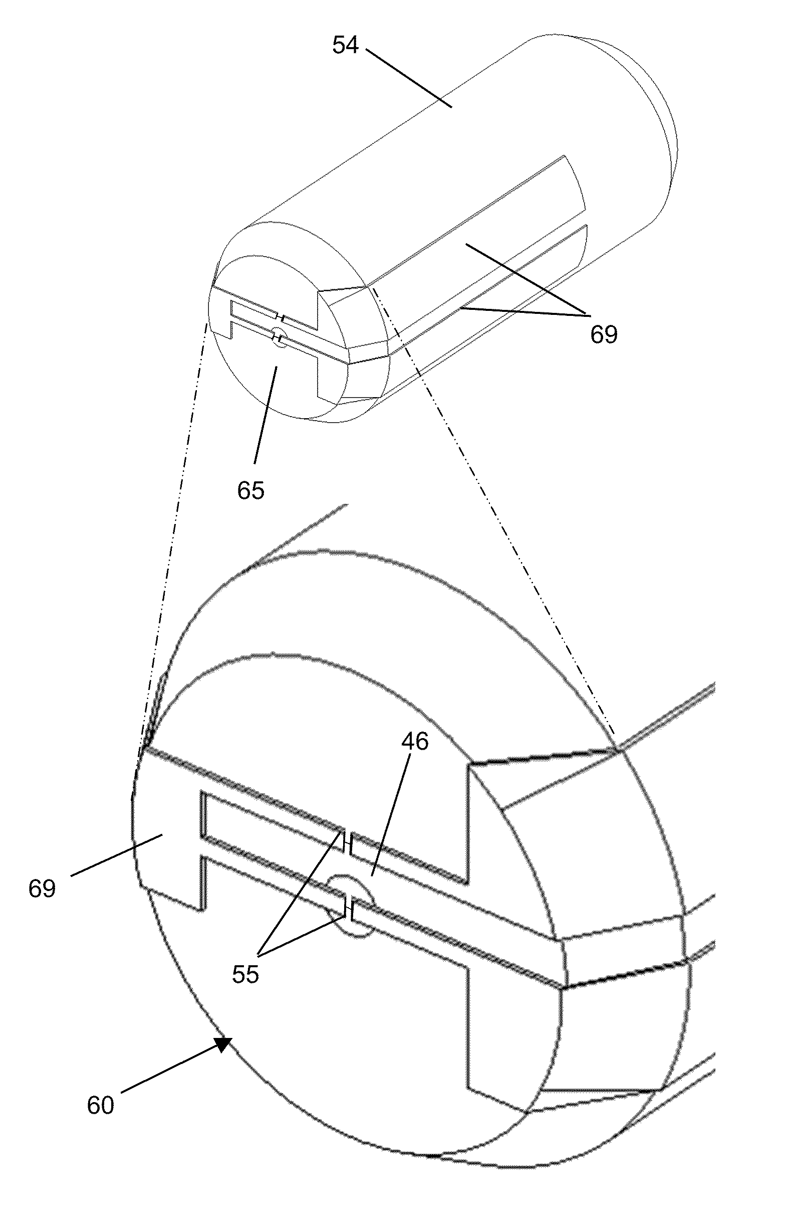
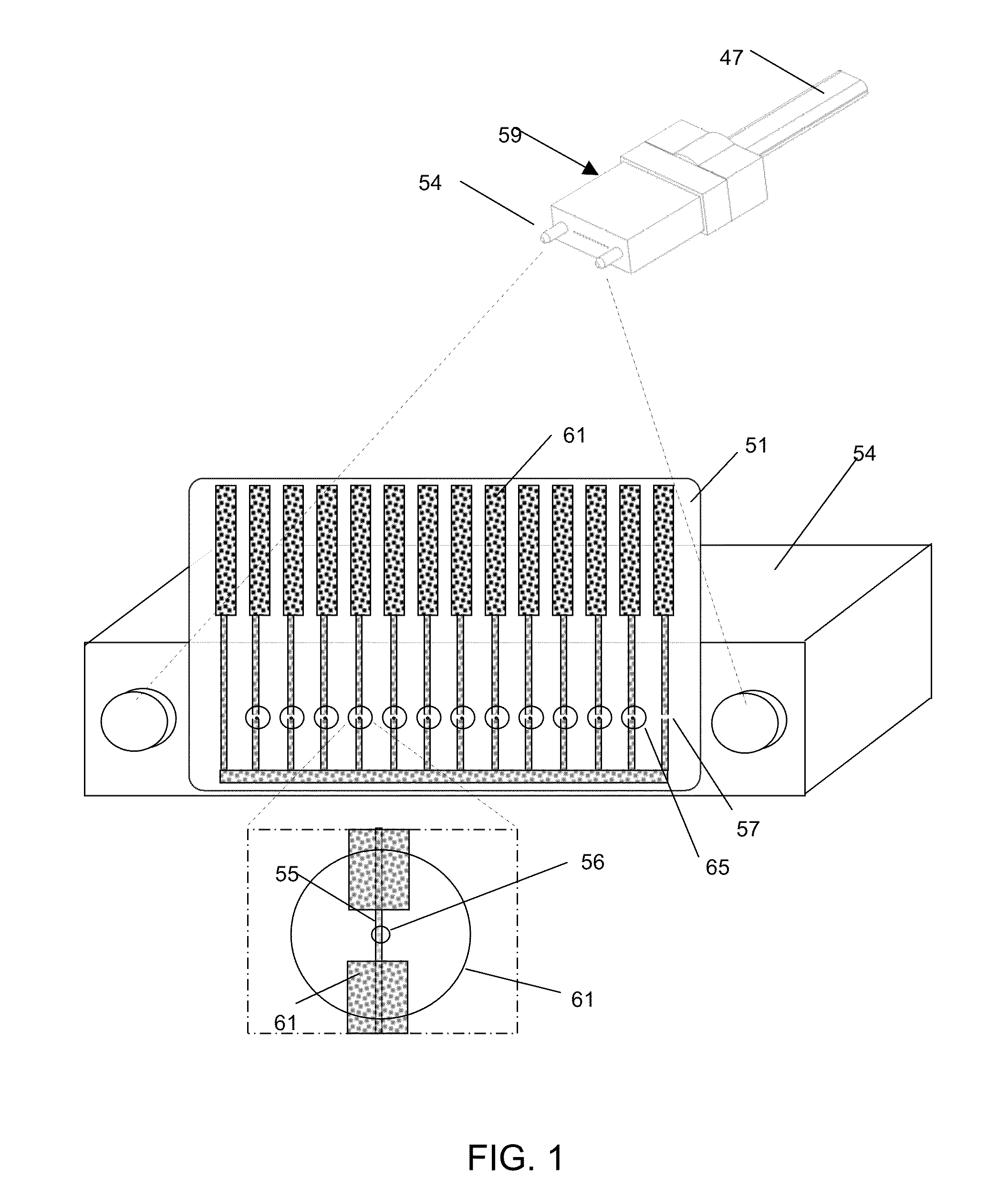
[0012]In accordance with the invention, the optical intensity transmitted in a confined mode is measured with minimal interference or attenuation. Ideally, optical intensity is measured at the core of the fiber to eliminate the loss of power inherent when coupling light out of the fiber and onto a photodiode. This need arises when trying to determine signal levels in optical fibers. By disposing microwires or nanowires transversely across the light-guiding section of the fiber, this minute wire traverses the optical path of the optical fiber. The detector wire is receptive to and exhibits a response proportional to the transmitted optical intensity, rather than optical power. The wire's geometry and material characteristics are selected to not interfere substantially with transmission, yet to absorb adequate energy for signal detection. These microwires and nanowires, which can be called “traces”, are formed as geometric patterns lithographically produced in a thin conductive layer such as indium tin oxide (ITO). Traces are of a configuration and size to absorb approximately 1% to 10% of the intersected radiation, depending on thickness, in the visible and infrared wavelength ranges. The trace element is thermally excited when the optical intensity passing through the trace is about 1 mW / mm2 or more, regardless of the total optical power of the beam. A proportional resistance change is generated by thermal heating in the element and is measured electronically, with adequate signal-to-noise ratio, by using circuit elements exterior to the transmitting core of the radiation propagating element. The optical energy propagated in the fiber waveguide is transmitted with nearly zero insertion loss, so that adequate signal strength is preserved.
[0013]In accordance with the invention, the patterned traces on the conductive layer may advantageously include anti-reflection coatings and / or thin film interference coatings to provide for optical filtering. Another feature of the invention resides in the fact that the detector traces can be reduced to nanometer scale dimensions, thus affording high-speed operation to demodulate wide bandwidth optical signals.
[0014]Further in accordance with the invention, multiple detectors can be disposed in an array at low cost throughout a fiber optic communication system. When detectors are connected between optical fibers of well defined mode-field diameters, they can measure not only optical intensity, but they also provide an indirect, yet accurate measure of optical power through a multiplicity of fiber optic junctions. Costs can be minimized by disposing the detectors on any of a wide variety of substrates of different materials and geometries. Detectors in accordance with the invention can also be used in monitoring and safety applications where unsafe optical power levels might exist.

Problems solved by technology

For instance, thermal detectors or bolometers absorb light within a low thermal mass structure, causing the film to heat up.
Advances in the design and manufacturing of fiber-coupled laser sources are leading to a proliferation of mainstream high power fiber applications and raising new laser safety issues.
As a result, the users of such a system are often unaware that the fiber is transmitting significant power, leading them to disconnect or handle the active fiber in an unsafe manner.
For instance, if the fiber is bent excessively, harmful levels of optical power can escape from the side of the fiber due to bend-induced outcoupling, analogous to a leaky pipe.
Current photodiode-based tap couplers are not well suited for this application because they are bulky, high loss and costly.

Method used


Image

  • In-line fiber optic monitors responsive to optical intensity
  • In-line fiber optic monitors responsive to optical intensity
  • In-line fiber optic monitors responsive to optical intensity

Examples


example application

Automated Network Monitoring

[0071]In a further example, the unique features of this detector element enable optical intensity, and by extension, optical power, to be measured through fiber optic junctions in a low cost fashion. This fundamental hardware component enables advanced self-monitoring and self-diagnosing network architectures can be realized for Fiber-to-the-Home networks and data centers, in which automation is applied to improve operational efficiencies and service quality / response. FIG. 9 illustrates in block diagram form an automated network management system with integral optical monitors 52 associated with each fiber optic interconnection 42. Through suitable electronic calibration, the optical monitors 52 disclosed herein produce an analog voltage proportional to throughput optical power. These analog signals are time multiplexed onto one or more analog-to-digital conversion ports. The resulting digital data packets represent the optical power reading and the physi...


PUM


Abstract

Apparatus and methods to monitor optical intensity within optical fibers in a substantially non-invasive fashion are disclosed. Optical monitors are comprised of thin, conductive coatings applied to transparent substrates and patterned to form pairs of resistive elements, one of which intersects an optical beam propagating through optical fiber cables. Systems of distributed optical monitors interconnecting optical fiber links enable automated monitoring of the optical status across a communications networks.

Description

REFERENCE TO RELATED APPLICATIONS[0001]This application is based on Provisional Patent Application No. 61 / 119,504, filed on Dec. 3, 2008 and entitled “Transparent Nanowire Optical Detectors”, and is a Continuation-in-Part of U.S. patent application Ser. No. 11 / 865,731, filed on Oct. 2, 2007 and entitled “Protective Fiber Optic Union Adapters”.FIELD OF THE INVENTION[0002]This invention relates to optical systems comprised of fiber optic cables transmitting illumination and / or signals, and more particularly, to devices enabling distributed measurements of the optical intensity and power transmitted within fiber optic cables.BACKGROUND OF THE INVENTION[0003]A wide range of optical detectors have been developed to detect visible and infrared illumination, characterized by the use of a highly absorbing detector thin film or substrate [Dereniak and Boreman, “Infrared Detectors and Systems”, Wiley (1996)]. Typically, the active layer (e.g., p-n junction) of these detectors absorbs a majori...

Claims


Application Information

Patent Timeline
Patent Type & Authority Patents(United States)
IPC IPC(8): G02B6/38G02B6/42
CPCG02B6/3825G02B6/3846G02B6/3897G02B6/4202G02B6/3885G02B6/3895G02B2006/4297
Inventor KEWITSCH, ANTHONY
Owner TELESCENT
Why Eureka
Try Eureka