
Magnetorheological fluid composition and method for forming the same

a technology of magnetic fluid and composition, applied in the direction of magnetic materials, magnetic bodies, electrical devices, etc., can solve the problems of not being able to change the density of particles, the brown motion cannot stop particle precipitation and aggregation, and the brown motion cannot resist particle precipitation in the carrier fluid, etc., to achieve high yield stress, variable viscosity friction, good dispersion

Inactive Publication Date: 2015-09-08
NAT TAIPEI UNIV OF TECH
View PDF4 Cites 6 Cited by
  • Summary
  • Abstract
  • Description
  • Claims
  • Application Information

AI Technical Summary

Benefits of technology

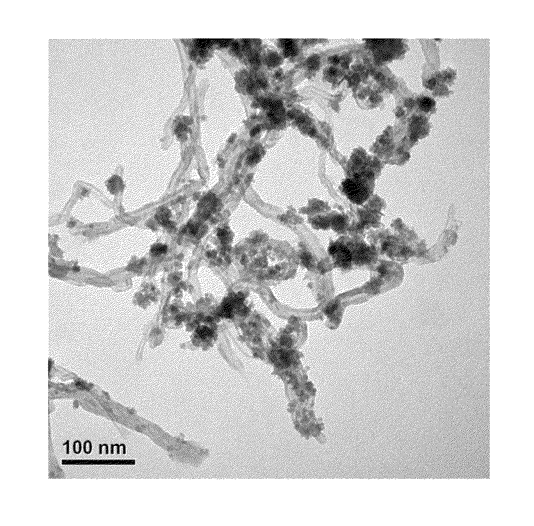
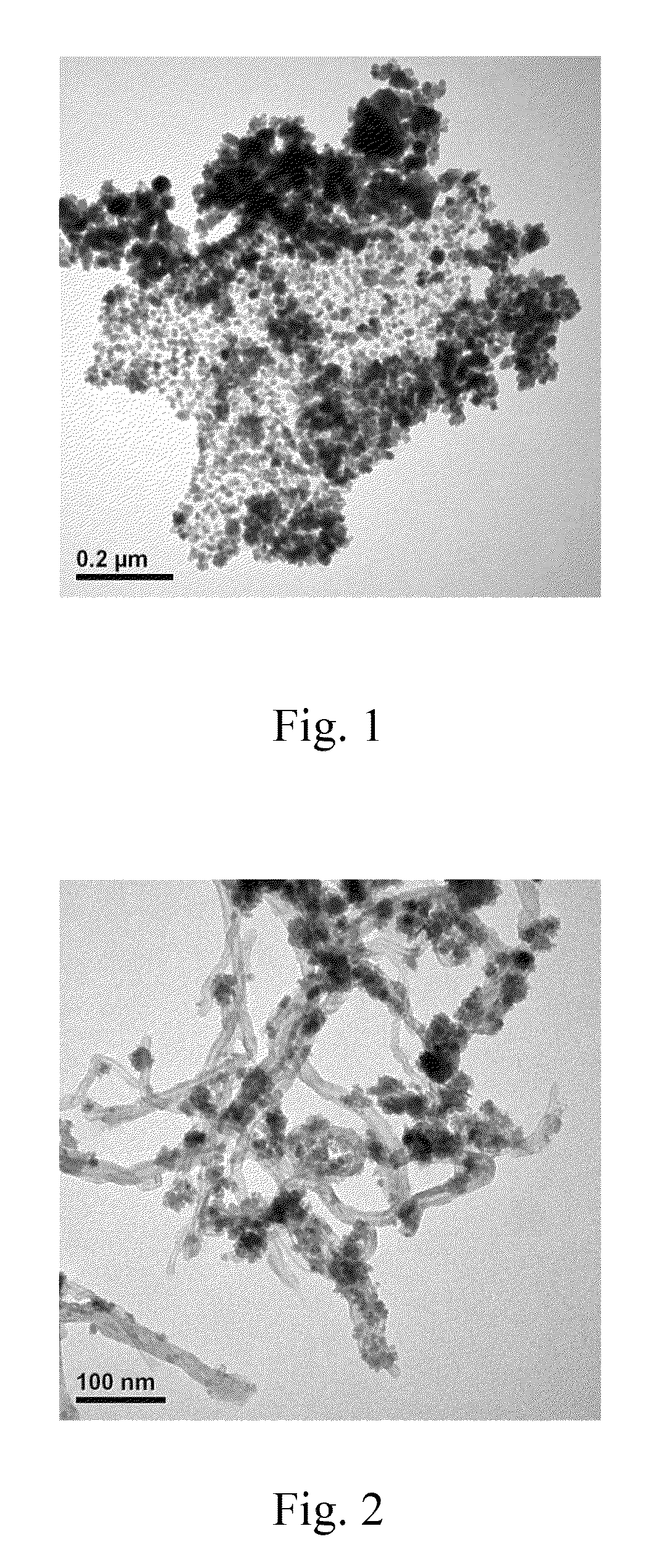
[0020]According to the magnetorheological fluid composition and the method for forming the same of the present invention, a nano-magnetic-responsive composite is used so as to make the magnetorheological fluid composition have a high yield stress and good dispersion and have variable viscous friction with the change of the magnetic field applied thereon. Thus, the magnetorheological fluid composition can be applied in a smart damper for various devices because of its damping-controllable property. Furthermore, because of its variation in viscosity, the magnetorheological fluid composition can be applied in substance separation, loading or sealing for mechanical devices.

Problems solved by technology

That is, if viscous friction of the fluid is too small, it is over loaded for large energy release to have the residual energy keep vibrating.
However, the magnetic responsive particles in the magnetorheological fluid have larger particle size and thus Brownian motion cannot stop particle precipitation and aggregation.
But, such a method cannot change the density of particles and thus cannot resist particle precipitation in the carrier fluid because these magnetic responsive particles usually have much larger density than that of the carrier fluid.
Not only production complexity but also production cost is increased.

Method used


Image

  • Magnetorheological fluid composition and method for forming the same
  • Magnetorheological fluid composition and method for forming the same

Examples


example 1

Preparation of Magnetorheological Fluid Composition I

[0037](1) Acid-Treated Carbon Nanotubes

[0038]A conventional acid washing method was used. Carbon nanotubes (a ratio of the length (L) to diameter (D) (L / D) was about 500˜1000, purchased from T-Tek Co., LTD.) were dipped into nitric acid or sulfuric acid solution and then processed by supersonic oscillation to obtain the acid-treated carbon nanotubes grafted with carboxyl moieties (—COOH).

[0039](2) Preparation of Modified Carbonyl Iron Nanoparticles

[0040]4-Aminobenzoic acid 2 g (purchased from SIGMA) was mixed with deionized water 33.5 ml and stirred for 1˜3 hrs by a magnetic stirrer. Carbonyl iron powder (purchased from BASF) 5.3 g was added to form a mixture solution. The mixture solution was under supersonic oscillation for 12˜20 mins and deionized water was used to wash away 4-Aminobenzoic acid. Strong magnet was used to attract all black solids and the upper layer solution was discarded. The above washing process was repeated ...

example 2

Preparation of Magnetorheological Fluid Composition II

[0045]Except for having solid content of 43 wt %, example 2 used the same procedure as example 1 so as to obtain the magnetorheological fluid composition II.

example 3

Preparation of Magnetorheological Fluid Composition III

[0046](1) Acid-Treated Graphene

[0047]A conventional acid washing method was used. By using the same method as Example 1, graphene (obtained from Taiwan Texitile Research Institute) was dipped into nitric acid or sulfuric acid solution and then processed by supersonic oscillation to obtain the acid-treated graphene grafted with carboxyl moieties (—COOH).

[0048](2) Preparation of Modified Carbonyl Iron Nanoparticles

[0049]By using the same method as Example 1, 4-aminobenzoic acid 2 g (purchased from SIGMA) was mixed with deionized water 33.5 ml and stirred for 1˜3 hrs. Carbonyl iron powder (purchased from BASF) 5.3 g was added to form a mixture solution. The mixture solution was under supersonic oscillation for 1220 mins and deionized water was used to wash away 4-Aminobenzoic acid. Strong magnet was used to attract all black solids and the upper layer solution was discarded. The above washing process was repeated until the upper la...


PUM

PropertyMeasurementUnit
diameteraaaaaaaaaa
yield stressaaaaaaaaaa
diameteraaaaaaaaaa

Abstract

The present invention provides a magnetorheological fluid composition and method for forming the same. The magnetorheological fluid composition comprises a carrier fluid and a nano-magnetic-responsive composite dispersed uniformly in the carrier fluid. The nano-magnetic-responsive composite is formed by having carbonyl iron microparticles react with a grafting agent to form a modified carbonyl iron nanoparticles and blending the modified carbonyl iron nanoparticles with acid-treated graphene or carbon nanotubes.

Description

BACKGROUND OF THE INVENTION[0001]a. Field of the Invention[0002]The invention relates to a magnetorheological fluid composition and method for forming the same.[0003]b. Description of the Related Art[0004]Generally, a shock absorber or damper at least comprises a shock absorbing mechanism, for example, formed by a spring and an oil cylinder where the spring is used to absorb the instant vibrating energy and then releasing the energy after absorption is consumed by viscous friction of the fluid (oil) in the oil cylinder. The spring in the damper determines the capability of shock absorption but in practice the vibrating energy varies while the fluid (oil) has only a certain range of energy loading. That is, if viscous friction of the fluid is too small, it is over loaded for large energy release to have the residual energy keep vibrating. On the contrary, if viscous friction of the fluid is too large, it is not sensitive for small energy release to cause failure in shock absorption. ...

Claims


Application Information

Patent Timeline
Patent Type & Authority Patents(United States)
IPC IPC(8): H01F1/44
CPCH01F1/445H01F1/447
Inventor RWEI, SYANG-PENG
Owner NAT TAIPEI UNIV OF TECH
Learn More