VTFT with extended electrode

a technology of extending electrodes and electrodes, applied in the field of semiconductor devices, can solve the problems of high cost and high end equipment, limited feature size obtainable using traditional processing methods, and high cost of high-end equipmen

Inactive Publication Date: 2015-09-29
EASTMAN KODAK CO
View PDF20 Cites 2 Cited by
  • Summary
  • Abstract
  • Description
  • Claims
  • Application Information

AI Technical Summary

Benefits of technology

[0067]Briefly turning to FIGS. 2a and 2b, a schematic cross-sectional view of the electrically conductive gate structure 120, including post 20, cap 30, and gate layer 125, is shown in FIG. 2a, taken along the line A-A′ of the plan view shown in FIG. 2b. As shown in FIG. 2b, the post 20 has a length dimension 35 and a width dimension 25. The cap 30 extends beyond the post 20 in the length and width dimensions as shown in FIGS. 2a and 2b. The gate layer 125 conformally covers the post 20 and cap 30, and extends beyond the base of the post 20 to contact substrate 110. In other example embodiments of the invention, the gate layer 125 covers only the edges 40 of the post 20 in the areas of the first reentrant profile 140, and optionally the second reentrant profile 145. The polymeric material post 20 has a height dimension 45 extending away from the substrate 110. The height of the post defines the shortest obtainable channel length for vertical transistor 100 or 200. It is an advantage of the present invention that channel lengths are easily obtainable using the post 20 and cap 30 structure that are not easily obtainable using standard photolithography. It is preferred that the height of the post 20 that is less than or equal to 10 microns. In some example embodiments, the post 20 is less than or equal to 2 microns. In still other example embodiments, the post 20 is less than or equal to 1 micron, and can be as short as 0.3 microns to minimize the vertical transistor channel length. The cap 30 extends beyond the edge of the post 20 and, therefore, should have structural integrity. It is preferred that the cap 30 extends beyond the edge 40 of the post 20 by a distance that is less than the height 45 of the post 20.
[0068]Returning now to FIGS. 1a and 1b, insulating layer 130 conforms to the reentrant profiles 140 and 145 of transistors 100 and 200. Insulating layer 130 is in contact with the gate layer 125. As insulating layer 130 is a conformal insulating material layer, it can be said to coat and maintain the reentrant profiles 140 and 145. Insulating layer 130 is often referred to as a dielectric material layer, or simply a dielectric layer, and can be formed of a single material layer or multiple dielectric material layers. Preferably the insulating layer 130 is a thin film inorganic dielectric material layer. Semiconductor material layer 150 is in contact with the insulator layer 130 and also conforms to and maintains the shape of the first reentrant profile 140 and second reentrant profile 145 of transistors 100 and 200. As such, semiconductor material layer 150 is a conformal semiconductor material layer. Preferably the semiconductor layer 150 is a thin film inorganic semiconductor material layer.
[0069]The source and drain of transistor 100, 200 have conventionally accepted meanings, and either the first electrode 180 or the second electrode 170 can be designated the source (or drain) as is required by the application or circuit. The first electrode 180, second electrode 170 and third electrode 175 can be a single conductive material, as shown in FIG. 1a, or can include any number of conductive material layers (commonly referred to as a conductive layer stack). The first electrode 180 is located in contact with a first portion of the semiconductor layer over the cap. The second electrode 170 electrode is located in contact with a second portion of the semiconductor layer over the substrate and not over the post, as shown in FIG. 1a. The first electrode 180 and second electrode 170 electrode define a first channel in the semiconductor layer between the first electrode 180 and second electrode 170. The first electrode 180 has an edge into the plane of FIG. 1a along the line defined by point C1. As shown in FIG. 1a, point C1 is above the substrate surface. Similarly, the second electrode 170 has an edge into the plane of FIG. 1a along the line defined by point C1′. As shown in FIG. 1a, the first electrode 180 and second electrode 170 electrodes are different distances from the substrate surface (see points C1 and C1′). Stated another way, the distance between the first electrode 180 and second electrode 170 is greater than zero when measured orthogonal to the substrate surface. Together with the gate structure, insulating layer, and semiconductor layer, this forms the first transistor 100, including a portion of the channel which is vertical with respect to the substrate surface.
[0070]As shown in FIG. 1a, the vertical TFT 100 is formed in series with vertical TFT 200. In this configuration there are three electrodes, a second electrode 170 for TFT 100 not over the post 20, the shared first electrode 180 over the cap 30 and post 20, and a third electrode 175 for TFT 200 not over the post 20 (on the side opposite the post 20 from the second electrode 170 electrode of TFT 100. As shown, the post 20 has another edge 40 along the height dimension and the cap 30 extends beyond the other edge 40 of the post to define a second reentrant profile 145. The third electrode 175 is located in contact with a third portion of the semiconductor layer over the substrate 110 and not over the post 20, and adjacent to the second reentrant profile 145. The distance between the first electrode 180 and third electrode 175 is greater than zero when measured orthogonal to the substrate surface. The first electrode 180 and the third electrode 175 define a second transistor 200 having a channel in the semiconductor layer between the first electrode 180 and the third electrode 175.
[0071]Accordingly, the first electrode 180 and the second electrode 170 define the channel of the first TFT 100, and the third electrode 175 and the first electrode 180 define the channel of the second TFT 200. The configuration shown in FIGS. 1a and 1b allows contact to the vertical transistors 100 and 200 to be made on the substrate level so the transistors are operated in series, rather than making connection at the top of the electrically conductive gate structure 120. It should be understood that the present invention includes a single vertical transistor where the electrodes are disposed as 170 and 180 in FIG. 1a. As shown, the electrically conductive gate structure 120 functions as the gate for transistors 100 and 200. In some example embodiments of transistor 100, electrode 170 functions as the drain of transistor 100 and electrode 180 functions as the source of transistor 100. In other example embodiments of transistor 100, electrode 170 functions as the source and electrode 180 functions as the drain. The semiconductor device is actuated in the following manner. After transistor 100 is provided, a voltage is applied between the electrode 170 and the electrode 180. A voltage is also applied to the electrically conductive gate structure 120 to electrically connect the electrode 170 and the electrode 180.
[0072]Still referring to FIGS. 1a and 1b, vertical transistor 200 is formed at the same time as vertical transistor 100 is formed. Transistor 200 can be actuated in the following manner. A voltage is applied between the electrode 175 and the electrode 180, which is shared with vertical transistor 100. A voltage is applied to the gate layer stack 120, which is shared with vertical transistor 100, to electrically connect the electrode 175 and 180.

Problems solved by technology

The feature size obtainable using traditional processing methods is limited by the resolution of the photolithography tools.
Currently the minimum feature size for large area display backplanes is around 0.5 microns, and requires expensive high end equipment.
For example, since it is not currently possible to put patterns directly on walls which are vertical with respect to a substrate surface, vertical wall patterning has been accomplished using a suitable temporary filler material to partially fill in a trench.
While there are many processes to deposit dielectric materials, few result in high quality films at these thicknesses.
There persists a problem of combining multiple SAD steps to form working devices.

Method used


Image

  • VTFT with extended electrode
  • VTFT with extended electrode
  • VTFT with extended electrode

Examples


examples

Description of the Coating Apparatus

[0164]The process of depositing the inorganic thin film layers of the following examples all employ a flow setup as described with reference to FIG. 66. The flow setup is supplied with nitrogen gas flow 81 that has been purified to remove oxygen and water contamination to below 1 ppm. The gas is diverted by a manifold to several flow meters which control flows of purge gases and of gases diverted through bubblers to select the reactive precursors. In addition to the nitrogen supply, air flow 90 is also delivered to the apparatus. The air is pretreated to remove moisture.

[0165]The following flows are delivered to the ALD coating apparatus: metal (zinc) precursor flow 92 containing metal precursors diluted in nitrogen gas; oxidizer-containing flow 93 containing non-metal precursors or oxidizers diluted in nitrogen gas; and nitrogen purge flow 95 composed only of the inert gas. The composition and flows of these streams are controlled as described be...

example i1

Inventive Example I1

Four Pixel with Printed VTFT

[0188]To fabricate Inventive Example I1, a glass substrate was provided and cleaned using an O2 plasma (100 W 0.3 Torr for 1 minute). Next, a 40 wt % solution of SU-8 2010 in cyclopentanone was spun for 10 sec at 500 rpm and ramped to a final spin of 30 sec at 2000 rpm. This coating was cured using a recipe consisting of a two minute pre-exposure hot plate bake at 95° C., 90 second blanket exposure, a two minute post-exposure hot plate bake at 95° C. and final hard bake at 225° C. for 5 minutes resulting in a 7500 Å film of cured SU-8.

[0189]Next, the surface of the SU-8 was treated with a 30 second O2 plasma to activate the surface of the SU-8. The inorganic cap was formed over the SU-8 layer using the combination of SAD and ALD. Selective area deposition was done using a patterned deposition inhibiting material layer using a Fuji Dimatix 2500 piezo-inkjet printer, as described in reference to Comparative Example C1 at the same 70 micr...

example i2

Inventive Example I2

Three Pixel with Printed VTFT Layer

[0197]Inventive Example I2 was formed using the same process, and on the same substrate, as Inventive Example I1. The only difference between Inventive Example I2 and I1, is that Inventive Example I2 had a 3 pixel wide pattern used to define the width of the transistor when forming the source and drain electrodes.

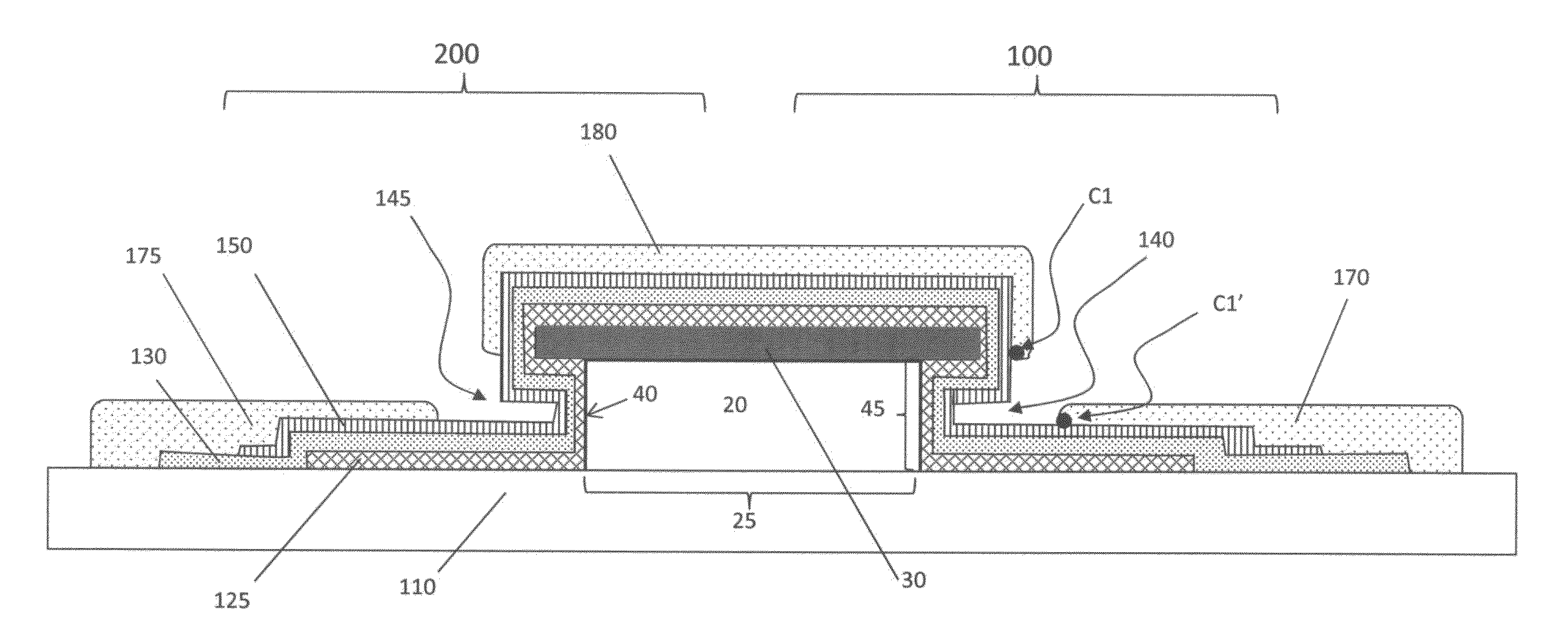
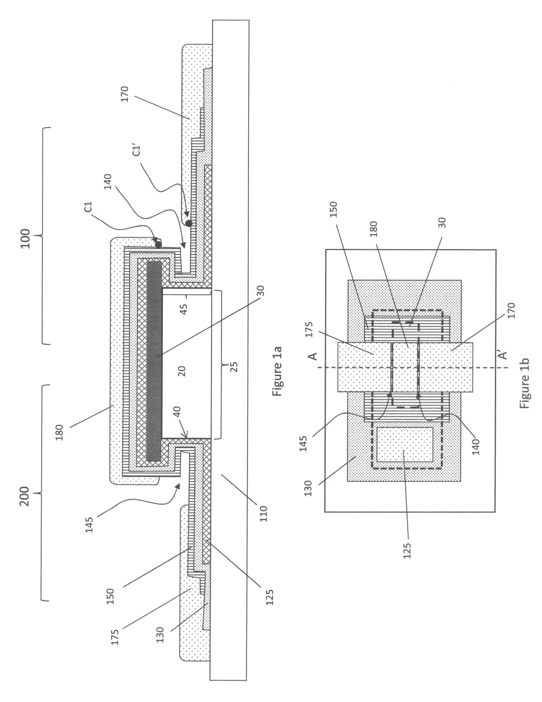
[0198]The VTFT of Inventive Example I2 is shown in FIGS. 68a through 68c. FIG. 68a is an optical micrograph of the complete VTFT. The first, second and third electrodes (180, 170 and 175) are labeled as in FIG. 1b for ease in understanding. The post and cap structure is identified by the outline of the cap 30. The optical micrograph of FIG. 68a illustrates the feature of the present invention where the channel defined by the first electrode and the second electrode including a width dimension and a length dimension, wherein the length dimension varies along the width dimension of the transistor. FIG. 68b is a SEM image ...


PUM


Abstract

A thin film transistor includes a polymeric material post on a substrate. An inorganic material cap, covering the top of the post, extends beyond first and second edges of the post to define first and second reentrant profiles, respectively. A conformal conductive gate layer is over the edge of the post, a conformal insulating layer is on the gate layer, and a conformal semiconductor layer is on the insulating layer in the first reentrant profile. A first electrode is in contact with a first portion of the semiconductor layer over the cap and extends to a location adjacent to the second edge. A second electrode is in contact with a second portion of the semiconductor layer not over the post, and adjacent to the first edge such that a distance between the first electrode and second electrode is greater than zero when measured orthogonally to the substrate surface.

Description

CROSS REFERENCE TO RELATED APPLICATIONS[0001]Reference is made to commonly-assigned, U.S. patent application Ser. No. 14 / 198,621, entitled “VTFT FORMATION USING CAPILLARY ACTION”, Ser. No. 14 / 198,636, entitled “VTFT FORMATION USING SELECTIVE AREA DEPOSITION”, Ser. No. 14 / 198,643, entitled “VTFT INCLUDING OVERLAPPING ELECTRODES”, Ser. No. 14 / 198,623, entitled “VTFTS INCLUDING OFFSET ELECTRODES”, Ser. No. 14 / 198,626, entitled “PATTERNING A STRUCTURAL POLYMER PATTERNING”, Ser. No. 14 / 198,628, entitled “VTFT WITH POLYMER CORE”, Ser. No. 14 / 198,630, entitled “FABRICATING VTFT WITH POLYMER CORE”, Ser. No. 14 / 198,647, entitled “OFFSET INDEPENDENTLY OPERABLE VTFT ELECTRODES”, Ser. No. 14 / 198,652, entitled “FORMING A VTFT USING PRINTING”, Ser. No. 14 / 198,568, entitled “VERTICALLY SPACED ELECTRODE STRUCTURE”, Ser. No. 14 / 198,664, entitled “FORMING VERTICALLY SPACED ELECTRODES”, all filed concurrently herewith.FIELD OF THE INVENTION[0002]This invention relates generally to semiconductor device...

Claims


Application Information

Patent Timeline
Patent Type & Authority Patents(United States)
IPC IPC(8): H01L29/06H01L29/10H01L29/423H01L29/786H01L29/66H01L27/148
CPCH01L29/78642H01L29/1037H01L29/4238H01L29/66969H01L29/42384H01L29/78603
Inventor ELLINGER, CAROLYN RAE
Owner EASTMAN KODAK CO
Why Eureka
Try Eureka