Method for manufacturing glass substrate for magnetic disk

a technology of magnetic disks and glass substrates, which is applied in the manufacture of base layers, record carriers, etc., can solve the problems of poor flatness (shape accuracy), thermal asperity trouble, and read errors of glass blanks, so as to improve the flatness of glass blanks and reduce internal strain of glass blanks

Active Publication Date: 2015-10-06
HOYA CORP
View PDF18 Cites 3 Cited by
  • Summary
  • Abstract
  • Description
  • Claims
  • Application Information

AI Technical Summary

Benefits of technology

[0010]In the vertical direct press method, immediately after a molten glass lump is placed on a lower die, only a contact surface with the lower die and a part close to the contact surface, of the molten glass lump, are rapidly cooled to be solidified. Since glass has low heat conductivity, an upper part of the molten glass lump (a part which comes into contact with an upper die) remains at a high temperature while the molten glass lump is in contact with the lower die. Therefore, in the case of the vertical direct press method, there is a gap in timing at which the molten glass lump is cooled to be solidified between the lower side and the upper side of the molten glass lump during a process in which the molten glass lump is formed into a glass blank. As a result, the molten glass lump is warped in a concave way, so that the flatness of the glass blank is increased (deteriorated). The gap in timing cannot be drastically suppressed in light of the press system of the vertical direct press method.
[0016]An object of the present invention is to provide a method for manufacturing a glass substrate for magnetic disk, the internal strain of which is reduced, without performing annealing treatment.
[0017]In view of the above-described problems, the present inventors have intensively conducted studies, and resultantly devised a novel press forming method. That is, in a method for manufacturing a glass blank according to this embodiment, a horizontal direct press method is employed in which a falling molten glass lump is press-formed using a pair of dies (press forming dies) arranged so as to face each other in a direction (horizontal direction) orthogonal to the falling direction of the molten glass lump. In the horizontal direct press method, the molten glass lump is not temporarily retained in contact with only one of a pair of dies until press forming is started with the molten glass lump sandwiched between a pair of dies. That is, in the horizontal direct press method, unlike the conventional direct press method, a difference in temperature, which is generated throughout the molten glass lump, can be reduced by the time when press forming of the molten glass lump is started. Thus, at the time point immediately before press forming is started, the viscosity distribution of the molten glass lump becomes very wide in the vertical direct press method, whereas the viscosity distribution of the molten glass lump is kept even in the horizontal direct press method of this embodiment. That is, in the horizontal direct method, a variation in the viscosity throughout the molten glass lump can be suppressed. Accordingly, in the horizontal direct press method, it is extremely easy to uniformly thinly draw the molten glass lump to be press-formed as compared to the vertical direct press method. Consequently, as compared to the case where a glass blank is prepared using the vertical direct press method, it is extremely easy to drastically suppress deterioration of the flatness when a glass blank is prepared using the horizontal direct press method.
[0019]As described above, the flatness of a glass blank prepared is improved by using a horizontal direct press method using a pair of dies. Here, even when the horizontal direct press method is used, heat of the molten glass lump is easily exhausted through the die at a surface portion of the molten glass lump which contacts the press forming surface of the die when the molten glass lump is cooled during press forming. On the other hand, at the central portion of the molten glass lump, heat of the molten glass is easily confined because this portion does not contact the press forming surface of the die. Therefore, there is a difference in temperature between the surface portion and the central portion of the molten glass lump. At this time, shrinkage associated with cooling of the molten glass lump precedes at the surface portion, and therefore a compressive stress layer (hereinafter, referred to as a residual stress layer) having a predetermined thickness is formed on the principal face of the glass blank after press forming. A tensile stress layer having a predetermined thickness is formed in the glass blank as a reaction to the residual stress layer at the surface portion, which has been formed previously. That is, it has become evident that in the press-formed glass blank, an internal strain by a compressive stress (hereinafter, referred to as a residual stress) and a tensile stress appropriate to the residual stress is generated across the thickness direction of the glass blank. It has become apparent that therefore, when the glass blank is subjected to machining using a scriber, a core drill or the like, the glass blank is broken when cut lines or the like formed by machining reach the tensile stress layer in the glass blank.
[0020]Accordingly, the present inventors have found that when at least a part of the residual stress layer formed on the principal face of the glass blank is removed, the residual stress in the residual stress layer and the tensile stress in the tensile stress layer can be decreased, so that the internal strain of the glass blank can be reduced.

Problems solved by technology

The magnetic head includes, for example, a magnetic resistance effect element, but such a magnetic head may cause a thermal asperity trouble as its specific trouble.
The thermal asperity trouble is a trouble in which when a magnetic head passes over a micro-irregularly-shaped surface of a magnetic disk while floating and flying, a magnetic resistance effect element is heated by adiabatic compression or contact of air, causing a read error.
However, the known vertical direct press method has the problem that the flatness (shape accuracy) of a glass blank prepared is poor.
Therefore, in the case of the vertical direct press method, there is a gap in timing at which the molten glass lump is cooled to be solidified between the lower side and the upper side of the molten glass lump during a process in which the molten glass lump is formed into a glass blank.
As a result, the molten glass lump is warped in a concave way, so that the flatness of the glass blank is increased (deteriorated).
The gap in timing cannot be drastically suppressed in light of the press system of the vertical direct press method.
Further, in the vertical direct press method, a mold release material ((mold) release agent) such as, for example, BN (boron nitride) should be attached to the die beforehand in order to prevent a situation in which the molten glass lump is stuck to the lower die and cannot be removed, but when such a mold release agent remains attached on the glass blank, the surface roughness cannot be decreased.
Preferably the temperatures of the upper die and the lower die are made identical wherever possible for preparing a glass blank having a good flatness, but when the mold release material is attached on the lower die, the heat conductivity of the lower die is deteriorated, and therefore it is difficult to uniformly cool both surfaces of the glass blank in a press forming process.
Accordingly, when a glass substrate for magnetic disk is manufactured by performing the annealing treatment, large-scale equipment and much time are required, so that manufacture costs of the glass substrate for magnetic disk are increased.
Further, when a glass blank with an internal strain generated during press forming is subjected to the annealing treatment, the internal strain of the glass blank is released, but the glass blank is deformed as the internal strain is released, and the flatness is then deteriorated.
It has become apparent that therefore, when the glass blank is subjected to machining using a scriber, a core drill or the like, the glass blank is broken when cut lines or the like formed by machining reach the tensile stress layer in the glass blank.

Method used


Image

  • Method for manufacturing glass substrate for magnetic disk
  • Method for manufacturing glass substrate for magnetic disk
  • Method for manufacturing glass substrate for magnetic disk

Examples


examples

[0155]The present invention will be further described below by way of Examples. However, the present invention is not limited to aspects described in Examples.

[0156](1) Preparation of Molten Glass

[0157]Raw materials were weighed so as to obtain a glass having the following composition, and mixed to obtain a mixed raw material. This raw material was put in a melting vessel, heated, melted, clarified and stirred to prepare a homogeneous molten glass free from foam and an unmelted substance. Foam and an unmelted substance, deposition of crystals, and contaminants such as a refractory material and platinum forming the melting vessel were not observed in the glass obtained.

[Composition of Glass]

[0158]Amorphous aluminosilicate glass having a composition including 50 to 75% of SiO2, 1 to 15% of Al2O3, 5 to 35% in total of at least one component selected from Li2O, Na2O and K2O, 0 to 20% in total of at least one component selected from MgO, CaO, SrO, BaO and ZnO and 0 to 10% in total of at ...

example 1

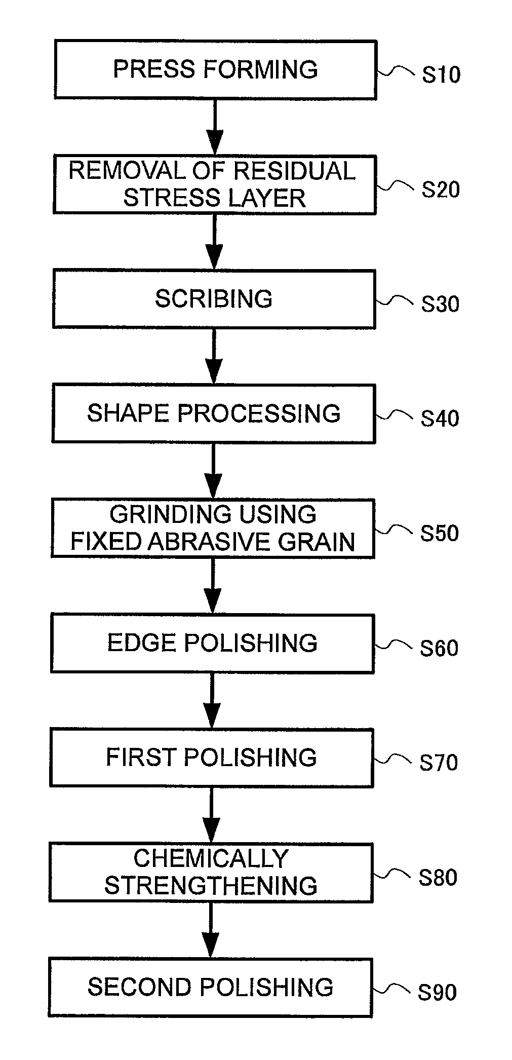
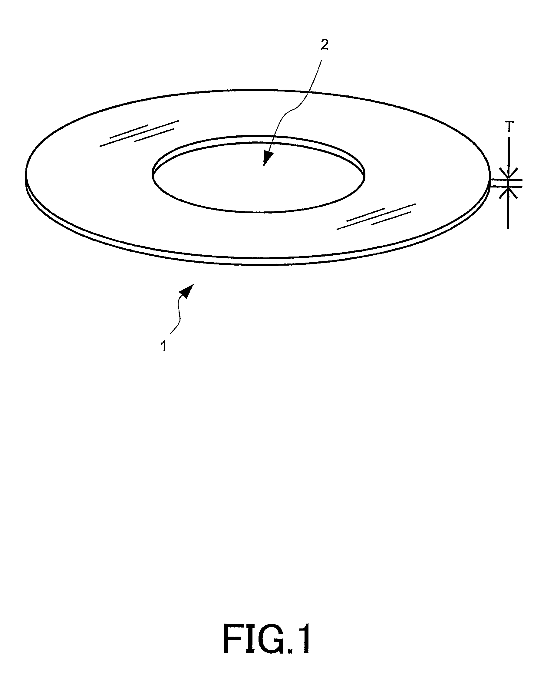
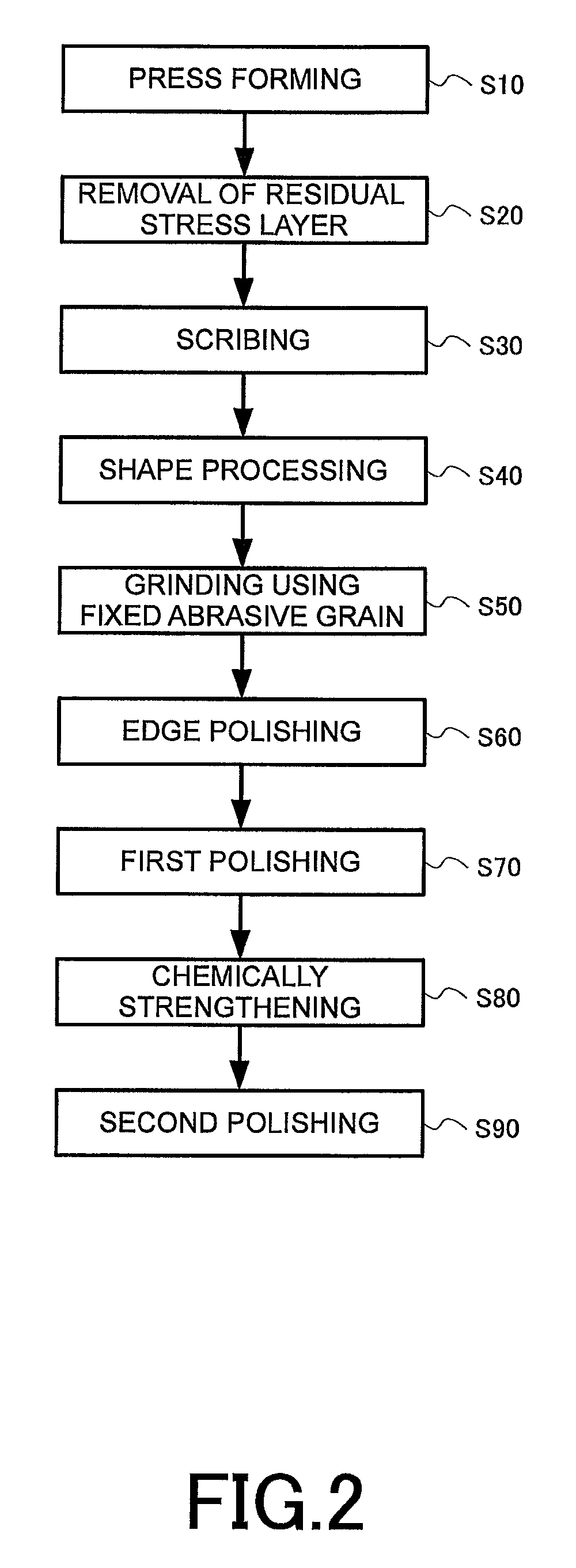
[0165]With regard to Example 1 illustrated in Table 1, surfaces of principal faces of a glass blank were removed by a predetermined amount, before the glass blank was scribed so as to be an annular glass substrate having an outer diameter of 65 mm, and a central hole diameter of 20 mm. The removal amounts for both surfaces in the principal faces were arranged to be the same each other. Removal amount for a single principal face was 3% of thickness of the glass blank.

example 2

[0166]With regard to Example 1 illustrated in Table 1, surfaces of principal faces of a glass blank were removed by a predetermined amount, before the glass blank was scribed so as to be an annular glass substrate having an outer diameter of 65 mm, and a central hole diameter of 20 mm. The removal amounts for both surfaces in the principal faces were arranged to be the same each other. Removal amount for a single principal face was 4% of thickness of the glass blank.


PUM

PropertyMeasurementUnit
viscosityaaaaaaaaaa
timeaaaaaaaaaa
flatnessaaaaaaaaaa

Abstract

A method for manufacturing a glass substrate for magnetic disk, the internal strain of which is reduced without performing annealing treatment, is provided. The method includes a forming process of forming a plate-shaped glass blank by pressing a lump of molten glass using a pair of dies, wherein the method includes: a removing process of removing at least a part of a residual stress layer formed on the principal face of the glass blank press-formed in the forming process; and a process of forming a donut-shaped glass substrate by subjecting the glass blank after the removing process to machining.

Description

CROSS-REFERENCE TO RELATED APPLICATIONS[0001]This U.S. National stage application claims priority under 35 U.S.C. §119(a) to Japanese Patent Application No. 2011-114460, filed in Japan on May 23, 2011, the entire contents of Japanese Patent Application No. 2011-114460 are hereby incorporated herein by reference.BACKGROUND[0002]1. Field of the Invention[0003]The present invention relates to a method for manufacturing a glass substrate for magnetic disk.[0004]2. Background Information[0005]Recently, a hard disk drive device (HDD) is incorporated in a personal computer or a DVD (Digital Versatile Disc) recording apparatus in order to record data. Particularly, in the hard disk device used in an apparatus such as the notebook personal computer based on portability, a magnetic disk in which a magnetic layer is provided on a glass substrate is used, and magnetic recording information is recorded in or read from a magnetic layer using a magnetic head (DFH (Dynamic Flying Height) head) that...

Claims


Application Information

Patent Timeline
Patent Type & Authority Patents(United States)
IPC IPC(8): G11B5/84
CPCG11B5/8404
Inventor ISONO, HIDEKITANINO, HIDEKAZUMURAKAMI, AKIRASATO, TAKASHISATO, MASAMUNE
Owner HOYA CORP
Why Eureka
Try Eureka