Reinforced matrix impregnated with electrolytes for molten carbonate fuel cell and fabrication method thereof

a technology of reinforced matrix and fuel cell, which is applied in the direction of cell components, final product manufacturing, sustainable manufacturing/processing, etc., can solve the problems of matrix not being able to retain electrolyte, reducing production yield, and method not yielding the expected effect, etc., to achieve simplified matrix manufacturing process, reduce the effect of thermal expansion coefficient difference between electrolyte sheet and matrix

Active Publication Date: 2015-10-13
DOOSAN HEAVY IND & CONSTR CO LTD
View PDF12 Cites 0 Cited by
  • Summary
  • Abstract
  • Description
  • Claims
  • Application Information

AI Technical Summary

Benefits of technology

[0010]According to the present invention, the electrolyte-impregnated matrix, which comprises both the electrolyte and the reinforcing particles including a metal and an oxide, is manufactured by adding the electrolyte, as required per unit cell of a fuel cell, and the reinforcing particles including the metal and the oxide, to slurry during the matrix preparation step, and subjecting the resulting slurry to a tape casting process. By doing so, the matrix stacking operation is facilitated, and the matrix manufacturing process is simplified. In addition, cracking caused by the difference in thermal expansion coefficient between an electrolyte sheet and the matrix can be suppressed, and thermal shock occurring during operation of the fuel cell stack can be reduced, thus improving the performance and lifetime of the fuel cell. Thus, the present invention has very excellent effects.

Problems solved by technology

However, in the method of using the ceramic fiber, agglomeration of the fiber occurs during the slurry preparation process, or the fiber is oriented in the direction of movement of the matrix sheet, so that defects occur during production of the matrix, thus reducing the production yield.
Also, the matrix provided according to this method has low resistance against the differential pressure between the air electrode and the fuel electrode, indicating that this method does not yield the expected effect.
Meanwhile, in the method of using the sintering aid, the bonding strength between the matrix particles shows a tendency to increase, but the fine pores of the matrix are changed to reduce the capillary force, so that the matrix cannot retain an electrolyte.
Meanwhile, in the method of using the porous metal support, the high surface pressure that is applied during the stacking process causes high stress around the support, indicating the support shows an adverse effect during pretreatment.
As a result, although the above-described methods aim to increase the mechanical strength of the matrix, these methods do not present a complete solution.

Method used


Image

  • Reinforced matrix impregnated with electrolytes for molten carbonate fuel cell and fabrication method thereof
  • Reinforced matrix impregnated with electrolytes for molten carbonate fuel cell and fabrication method thereof
  • Reinforced matrix impregnated with electrolytes for molten carbonate fuel cell and fabrication method thereof

Examples


examples 1 to 3

Fabrication of Electrolyte-Impregnated, Reinforced Matrix Using Reinforcing Metal Particles Together with Reinforcing Oxide Particles

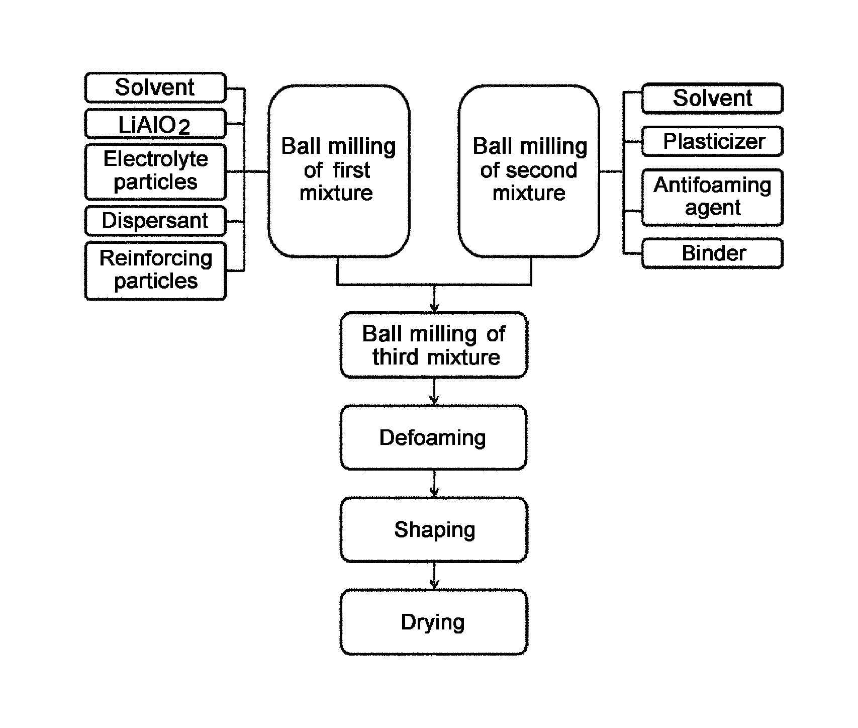
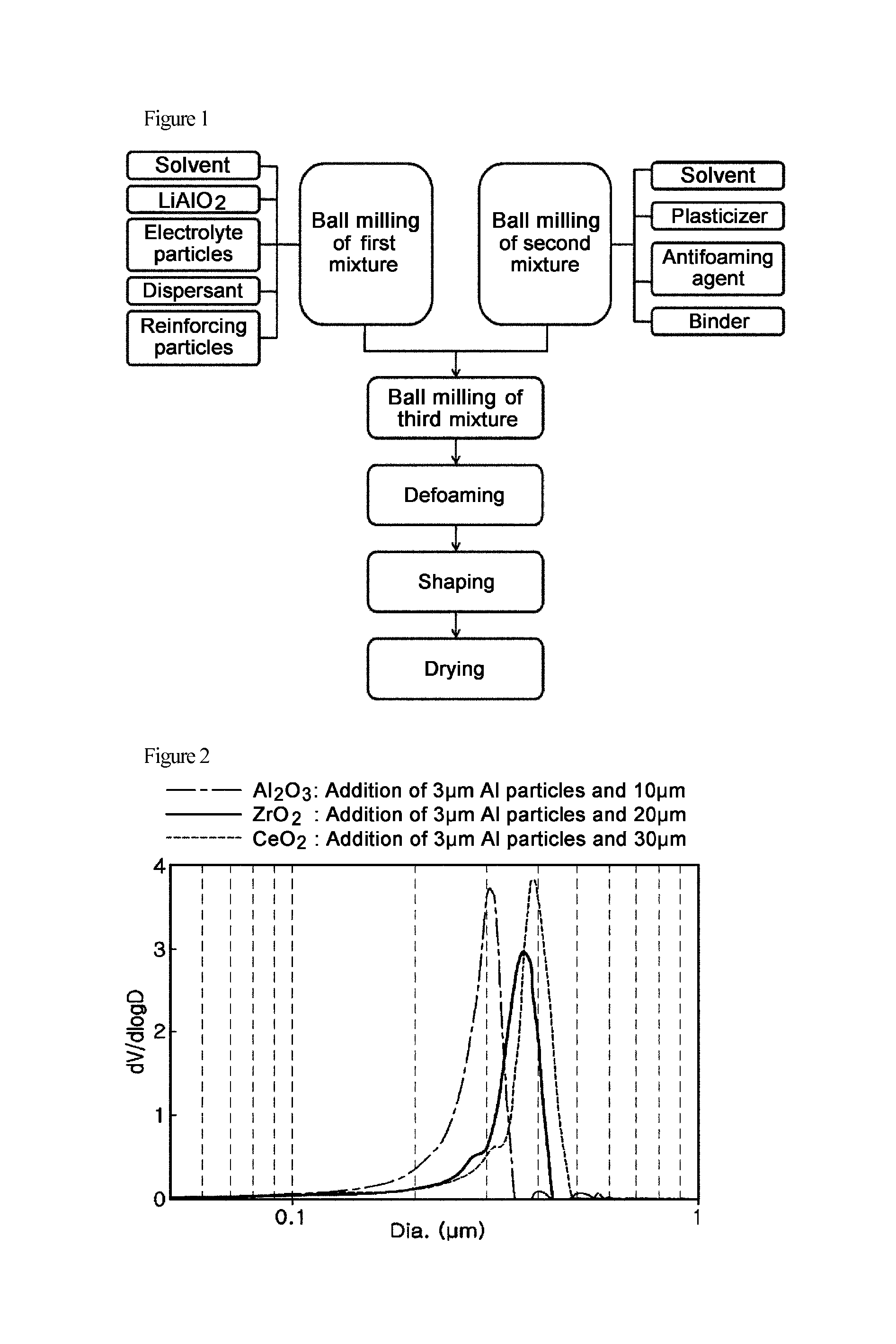
[0056]According to the composition ratio in Table 1 below, the following components were prepared: a mixed solvent of ethyl alcohol and toluene (ethyl alcohol:toluene=7:3 w / w) as a solvent; LiAlO2 powder as the main component of a matrix; Li2CO3 and K2CO3 as an electrolyte; commercial dispersant SN-D348 as a dispersant; 3-μm Al particles as reinforcing metal particles; and 10-μm Al2O3 particles, 20-μm ZrO2 particles or 30-μm CeO2 particles as reinforcing oxide particles. The above components were mixed with each other and ball-milled, thus preparing powder slurry. In this regard, the electrolyte was prepared by grinding each of Li2CO3 and K2CO3 to a size of 1 to or less and mixing the ground materials with each other at a ratio of 70 mol %:30 mol % and was used in an amount corresponding to 40 vol % of the total pore volume of a matrix to be manufactur...

experimental example 1

Differential Pressure Test of Reinforced Matrix of the Present Invention

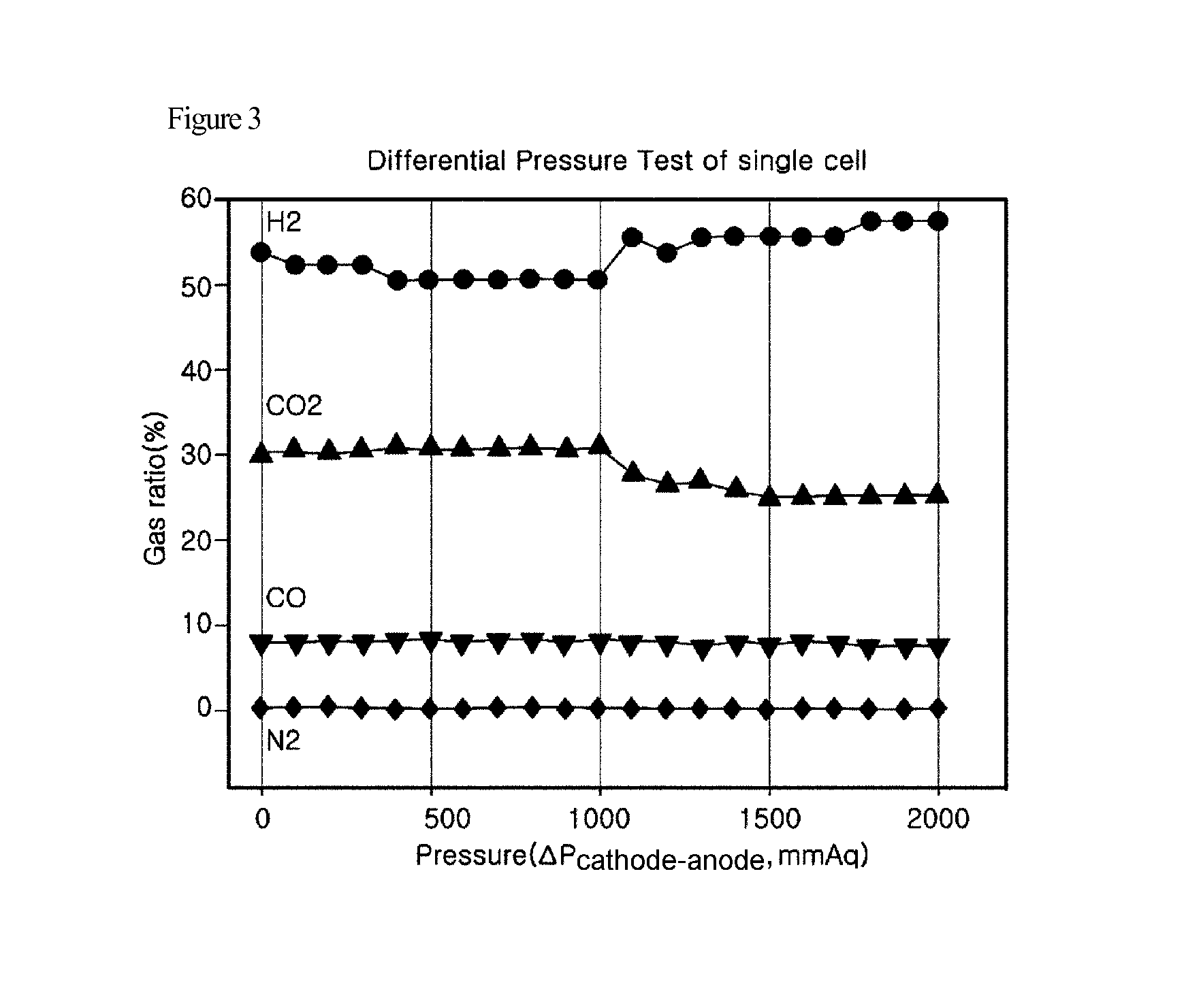
[0062]Each of the matrix reinforced with 3-μm aluminum particles and the matrix reinforced with 10-μm alumina particles, manufactured in Example 1, was subjected to a differential pressure test.

[0063]The differential pressure test was carried out using a single-cell system, in which the gas composition of an anode outlet was analyzed by GC while adjusting the pressure of a cathode outlet, and the durability of the matrix was evaluated based on whether N2 gas was detected.

[0064]The test results are shown in FIG. 3 which shows the results of detection of N2 gas in the anode outlet in a normal state in the pressure range from 0 to 2000 mmaq. As can be seen in FIG. 3, the reinforced matrix showed no detection of N2 gas in both the OCV state and the normal state even at a pressure of 2000 mmaq which is much higher than the design reference value of differential pressure, indicating that the reinforced matrix has exce...


PUM

PropertyMeasurementUnit
diameteraaaaaaaaaa
sizeaaaaaaaaaa
particle diameteraaaaaaaaaa

Abstract

The present invention relates to an electrolyte-impregnated, reinforced matrix for molten carbonate fuel cells and a manufacturing method thereof. According to the invention, the electrolyte-impregnated matrix, which comprises both the electrolyte and the reinforcing particles including a metal and an oxide, is manufactured by adding the electrolyte, as required per unit cell of a fuel cell, and the reinforcing particles including the metal and the oxide, to a slurry during the matrix preparation step, and subjecting the resulting slurry to a tape casting process. By doing so, the matrix stacking operation is facilitated, and the matrix manufacturing process is simplified. In addition, cracking caused by the difference in thermal expansion coefficient between an electrolyte sheet and the matrix can be suppressed, and thermal shock occurring during operation of the fuel cell stack can be reduced, thus improving the performance and lifetime of the fuel cell.

Description

TECHNICAL FIELD[0001]The present invention relates to an electrolyte-impregnated, reinforced matrix for molten carbonate fuel cells and a manufacturing method thereof, and more particularly to a method in which electrolyte powder and reinforcing particles are added to slurry during a process of manufacturing a matrix for a molten carbonate fuel cell stack so as to reinforce the matrix, thereby improving the mechanical stability of the stack, and a matrix manufactured therefrom.BACKGROUND ART[0002]In a conventional method, stacked unit cells are fabricated by mixing a binder and additives by a wet process to prepare a slurry, subjecting the slurry to tape casting to prepare an electrolyte sheet, and stacking the electrolyte sheet between an air electrode, a fuel electrode and a matrix to supply the electrolyte to each cell.[0003]However, the use of this method has disadvantages in that, because the electrolyte sheet is melted during pretreatment of the fuel cell stack so as to be abs...

Claims


Application Information

Patent Timeline
Patent Type & Authority Patents(United States)
IPC IPC(8): H01M8/14H01M8/02
CPCH01M8/145H01M8/0295Y02E60/526H01M2300/0051Y02E60/50Y02P70/50H01M8/02H01M8/14
Inventor SHIN, MI YOUNGRYU, BO HYUNMOON, HWANYOUN, JU YOUNGJUN, CHANG SUNGLEE, TAE WONMOON, KIL HO
Owner DOOSAN HEAVY IND & CONSTR CO LTD
Why Eureka
Try Eureka