Non-planer, image rotating optical parametric oscillator

a parametric oscillator and non-planer technology, applied in the field of nonlinear optical frequency conversion systems, can solve the problems of low conversion efficiency, small fraction of pump beams converted, inefficient generation of parametric beams (the idler and the signal) in a single path through the crystal(s) and other problems, to achieve the effect of wide wavelength tunability, simple low-cost, reliable and convenient operation

Active Publication Date: 2015-10-27
OPOTEK LLC
View PDF2 Cites 2 Cited by
  • Summary
  • Abstract
  • Description
  • Claims
  • Application Information

AI Technical Summary

Benefits of technology

[0018]This invention provides an OPO with unique attributes: wide wavelength tunability, a simple low-cost, reliable, easily operated means to orient the nonlinear crystal unit in the cavity while maintaining phase matching, high conversion efficiency while maintaining high damage threshold and good beam quality. This design is easy to fabricate and therefore makes OPO's of the present invention practical for a wide range of applications. In preferred embodiments, including Applicant's prototype, the OPO utilizes a non-planer ring-cavity design which rotates the signal beam image 90 degrees on each round trip. The polarization of the signal beam however is controlled so that, ahead of each pass through the non-linear crystals, the polarization of the beam is rotated back to its original orientation. In the prototype embodiment the ring cavity includes seven reflective surfaces including five mirrors, a roof prism (also known as a right angle prism). In addition a dichotic mirror is placed inside the ring cavity to introduce the pump beam into the cavity. A half wave plate corrects the polarization of the oscillating OPO beam. The prototype device includes a first non-linear crystal and a similar second non-linear crystal mounted side-by-side on a single rotating stage. The roof prism is positioned to cause the beam exiting the first crystal to be reflected into the second crystal and the two crystals are aligned so as to cause walk-off in the first of the two crystals to be cancelled by opposite walk-off in the second crystal. This OPO is designed to provide a high-energy output beam with excellent beam quality without damage to the OPO optics. In one form of the invention, the optical elements include a right angle prism to reflect the beam exiting the first crystal into the second crystal, two non-linear crystals, an output coupling mirror and 4 mirrors to reflect the signal beam in a closed ring. The seven reflecting surfaces are two back surfaces of the prism, the output coupler, and the four mirrors designed to rotate the resonating signal beam. In other preferred embodiments the oscillator could be designed to resonate the idler beam in which case the idler beam would be rotated. Rotation of the resonating beam greatly improves the quality of the output beam.
[0019]Applicant has constructed a prototype OPO that was pumped at 355 nm and generated very good beam quality, and with this prototype he has proven that oscillators designed in accordance with the present invention can operate over the entire visible spectrum and into the infrared region (410 nm to 2400 nm). The OPO can be designed to generate other wavelengths based on the choice of crystals and the pump laser.

Problems solved by technology

The generation of the parametric beams (the idler and the signal) in a single path through the crystal(s) is inefficient and only a small fraction of the pump beam is converted.
In this case the interaction between the pump and the parametric beams is limited to only half the time the parametric photons are oscillating inside the cavity, resulting in low conversion efficiency.
However, in a double path the pump intensity inside the crystals (and some of the optics) is very high and may result in damage.
Early OPO designs demonstrated poor beam quality, which was expressed by high divergence, typically on the order of 10 mRad, and non-symmetrical beam profiles.
The main reason for the poor beam quality was the high Fresnel numbers of these oscillators.
In substantially all conventional OPO cavity designs, increasing the ratio of beam diameter to cavity length reduces the beam quality.
This design is limited to a single pass through the crystals and therefore the efficiency of such an OPO is very low.Another method is to design an image rotation resonator in which the OPO beam rotates by 90 deg in each round trip in the cavity.
Most of the proposed oscillators have not been reduced to practice and, to Applicant's knowledge, the ones that have been reduced to practice have utilized a linear double path design, which increases the risk for damage.
However, in order to achieve these objectives, the cavity design imposes constrains which limit its practicality.
The device operates at a high efficiency, but it is most suitable as a single wavelength OPO as it is difficult to design one that will generate a wide range of wavelengths, as desired by most applications.
With this arrangement tuning would be very difficult requiring two separate tuning mechanisms.
As explained in U.S. Pat. No. 5,276,548 granted to Applicant, in critical phase matching configurations walk-off (which results as beams of different polarizations propagate through a birefringent crystals) can severely limit the effective gain in OPO devices.
Various constraints affect the design, and therefore the performance of presently available OPO devices.

Method used


Image

  • Non-planer, image rotating optical parametric oscillator
  • Non-planer, image rotating optical parametric oscillator
  • Non-planer, image rotating optical parametric oscillator

Examples


Embodiment Construction

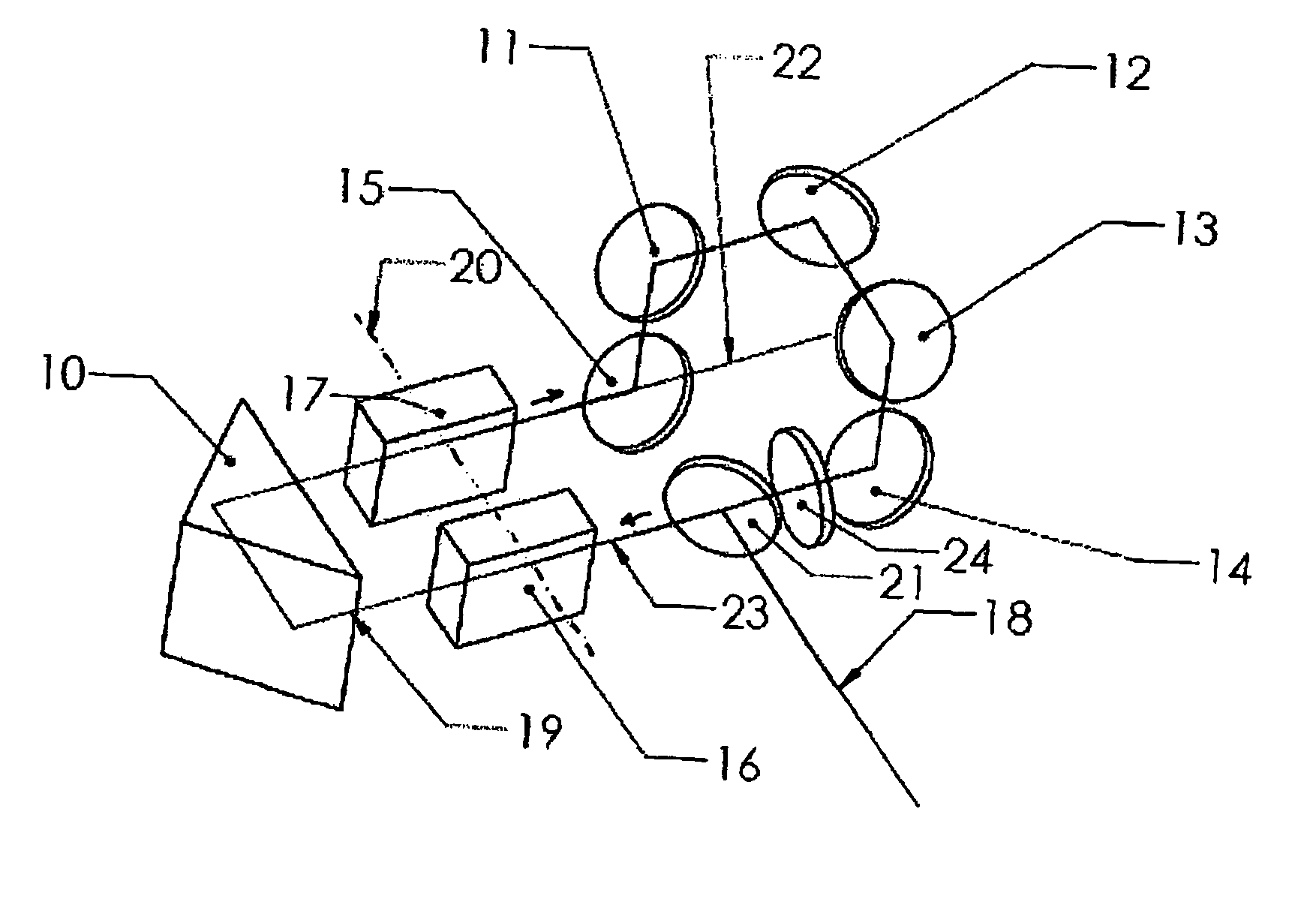
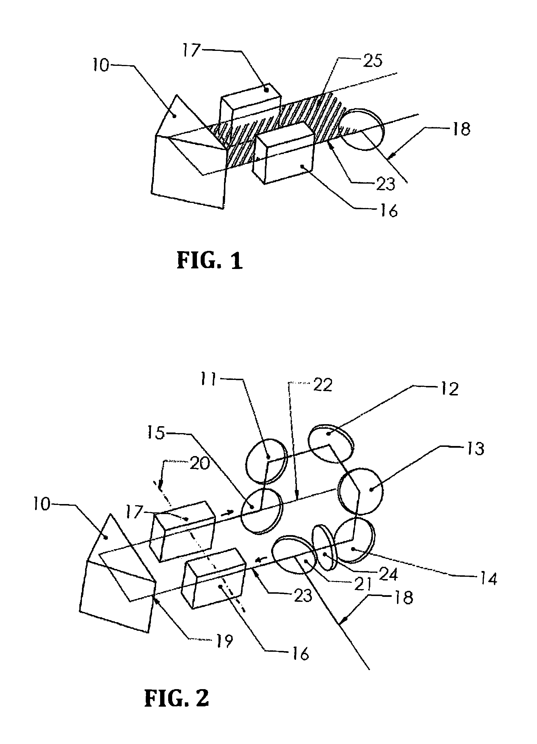
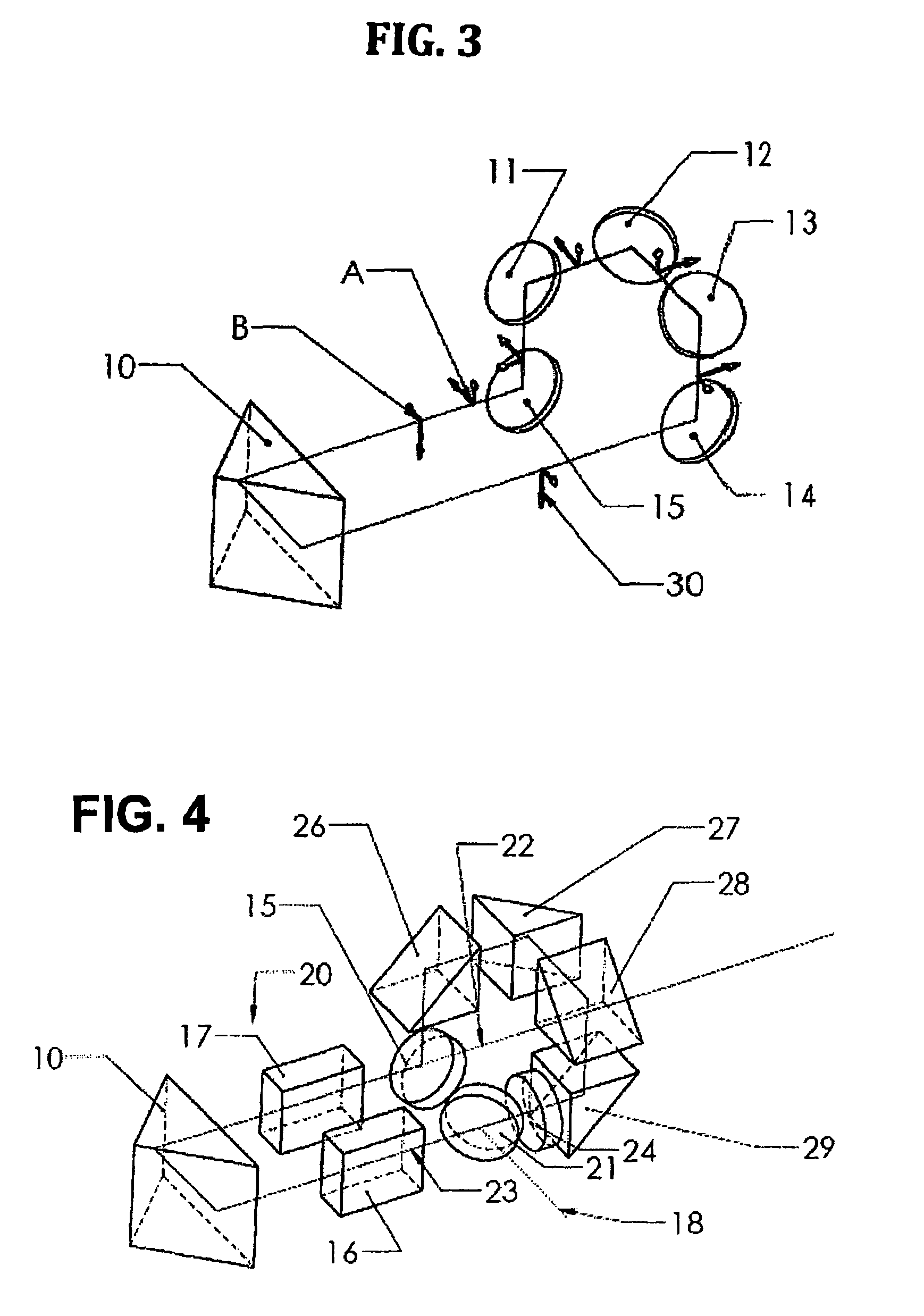
[0025]The following is a description of an OPO in which the signal beam is resonating: (The same resonator can be designed to oscillate the idler beam by selecting a different output coupler and exchanging the term signal with the term idler.)

[0026]The oscillator presented in FIG. 2 is formed by seven reflective surfaces. A roof prism (10), which provides two reflective surfaces, four mirrors (11,12,13,14) that are designed to reflect the signal beam, and mirror 15 with a dielectric coating designed to partially transmit the signal beam while maximizing the transmission of the idler beam and the pump beam. The pump beam 18 is introduced into the cavity by a mirror 21 that is designed to reflect the pump beam and transmit the signal and the idler beams. This mirror is not a part of the oscillator and serves only to inject the pump beam into the cavity. The cavity incorporates two non-linear crystals 16 and 17 that are mounted side by side on a rotation stage such that the walk-off in...


PUM

PropertyMeasurementUnit
angle of incidenceaaaaaaaaaa
fundamental wavelengthaaaaaaaaaa

Abstract

An Optical Parametric Oscillator (OPO) that includes optical elements located and oriented to form a non-planer, image-rotating ring cavity. To provide a high quality well shaped output beam, the OPO comprises a plurality of reflecting surfaces, designed to rotate the resonating beam by 90 degrees for each round trip in the cavity. Preferred embodiments include a first non-linear crystals and a similar second non-linear crystal mounted side-by-side on a single rotating stage. To minimize the adverse effects of walk-off, reflecting unit is positioned to cause the output of the first crystal to be reflected into the second crystal. The two crystals are aligned so as to cause walk-off in the first of the two crystals to be cancelled by opposite walk-off in the second crystal.

Description

CROSS REFERENCE TO RELATED APPLICATIONS[0001]This Application claims the benefit of U.S. Provisional Patent Application, Ser. No. 61 / 997,742, filed Jun. 7, 2014.FIELD OF THE INVENTION[0002]The present invention relates to the general art of non-linear optical frequency conversion systems, and in particular to such systems designed for improved beam quality, high conversion efficiency and high power.BACKGROUND OF THE INVENTION[0003]Optical Parametric Oscillators[0004]An Optical Parametric Oscillator (OPO) is a device employing one or more non-linear crystals which when pumped by a laser beam defining a pump wavelength, can generate coherent light at two different and longer wavelengths. The operation of an OPO typically requires a very high light intensity in the pump beam which is generally supplied by a very short pulse laser. In the OPO at least one non-linear crystal (such as BaB204, LiB305, LiNb03, KTiOP04 and others) is placed in an optical resonator. When the pump laser beam i...

Claims


Application Information

Patent Timeline
Patent Type & Authority Patents(United States)
IPC IPC(8): G02F1/39H01S3/00H01S3/16
CPCG02F1/39H01S3/0092H01S3/1643G02F2201/17G02F1/392G02F1/3551
Inventor MARGALITH, ELI
Owner OPOTEK LLC
Why Eureka
Try Eureka