
Circuitry and techniques for resistor-based temperature sensing

a resistor-based temperature and circuit technology, applied in the direction of thermometers with a/d converters, instruments, heat measurement, etc., can solve the problems of complex operation amplifiers, high current consumption, design and implementation challenges,

Active Publication Date: 2015-11-10
SITIME
View PDF53 Cites 26 Cited by
  • Summary
  • Abstract
  • Description
  • Claims
  • Application Information

AI Technical Summary

Benefits of technology

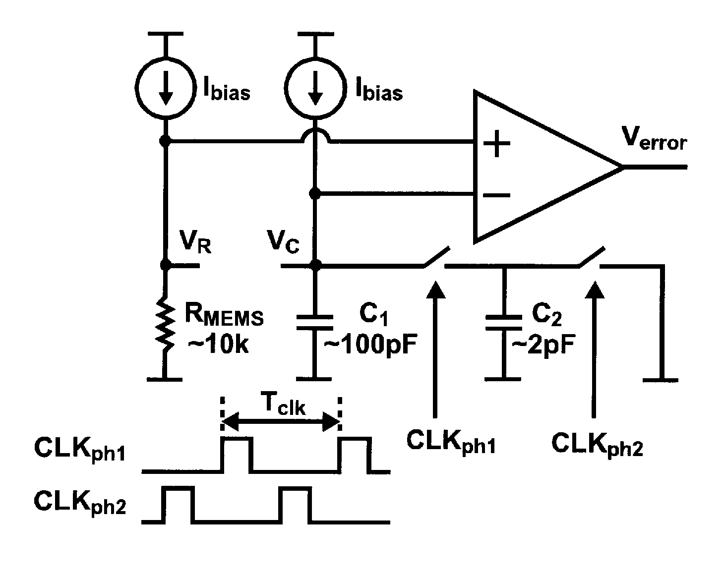
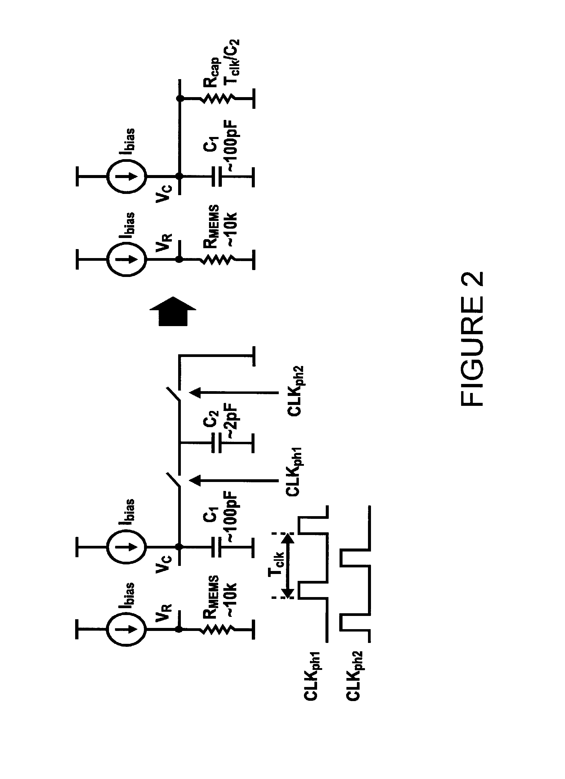
The present invention provides a temperature sensor with low noise, high accuracy, low power, and low area. The invention includes a switched capacitor network, a frequency divider, chopping circuitry, a pseudo-differential VCO-based analog-to-digital converter, and a feedback loop. The temperature dependent resistive element is a micromachined thermistor structure. The invention addresses the shortcomings of existing temperature sensors and improves performance for a wide variety of applications.

Problems solved by technology

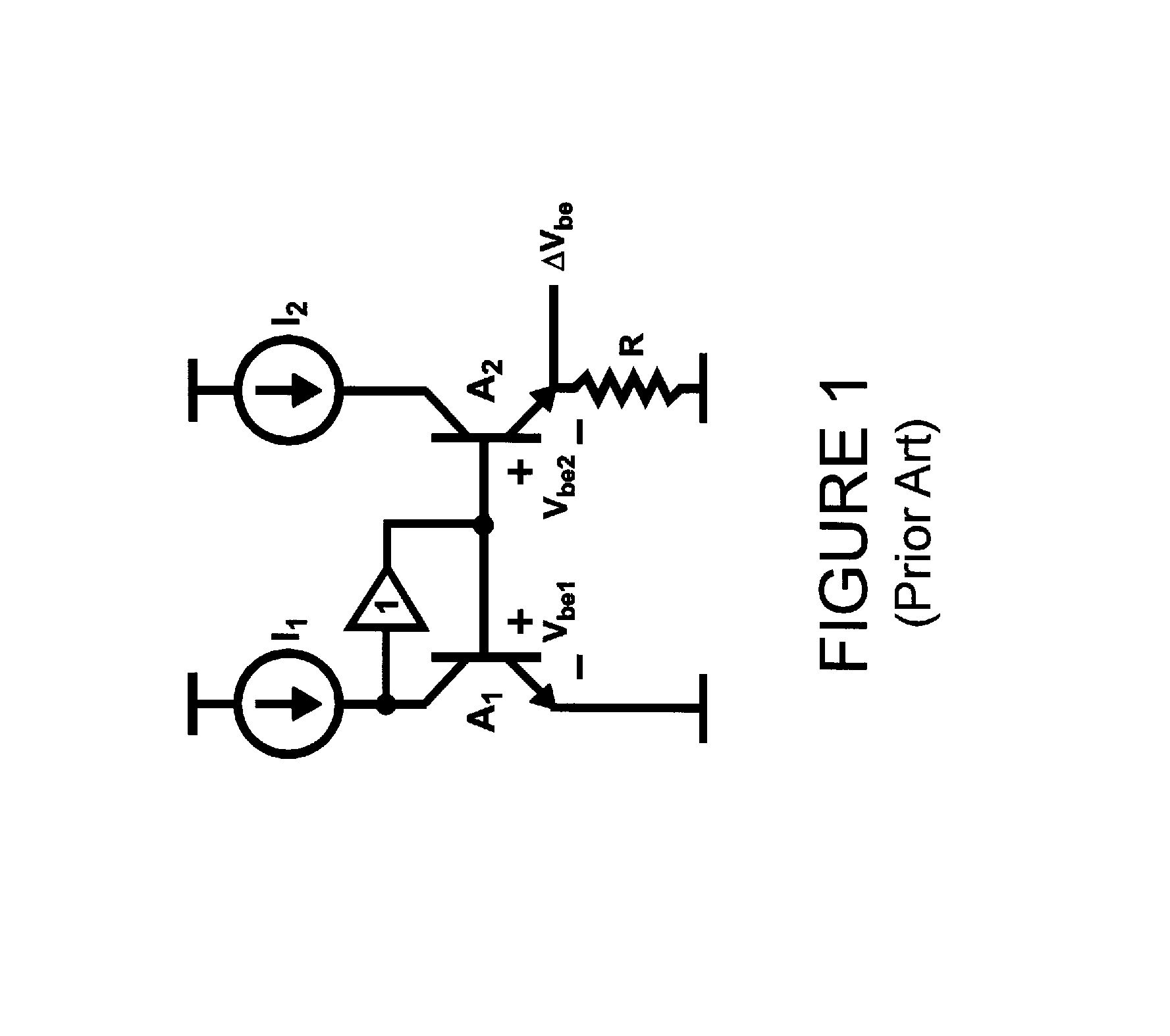
Despite the prevalence of the bipolar based temperature sensor approach, it presents design and implementation challenges when trying to achieve low noise.
From the design standpoint, achieving low noise is complicated by the fact that the temperature sensitivity of ΔVbe is quite small at approximately 180 microvolts per degrees Celsius.
When striving for faster sampling speeds, the presence of the larger capacitors requires higher current consumption in the operational amplifiers.
Thus, design for low noise has negative consequences of requiring larger area and power consumption, and, of course, also carries the cost of a difficult design effort.

Method used


Image

  • Circuitry and techniques for resistor-based temperature sensing
  • Circuitry and techniques for resistor-based temperature sensing
  • Circuitry and techniques for resistor-based temperature sensing

Examples


Embodiment Construction

[0043]It should be noted that there are many inventions described and illustrated herein. The present inventions are neither limited to any single aspect nor embodiment thereof, nor to any combinations and / or permutations of such aspects and / or embodiments. Moreover, each of the aspects of the present inventions, and / or embodiments thereof, for example, (i) a switched capacitor network that provides or creates a low noise adaptable reference resistor for comparison purposes, (ii) a frequency divider that is controlled by a digital Sigma-Delta modulator to achieve an accurately controlled switching frequency for the switched capacitor network, (iii) chopping circuitry and method to mitigate the effect of 1 / f noise and circuit offsets, (iv) a pseudo-differential VCO-based analog-to-digital converter (ADC) structure, or other ADC topology, to efficiently convert the analog error between the MEMS-based resistance value and the effective resistance of the switched capacitor network into ...


PUM

PropertyMeasurementUnit
switching frequencyaaaaaaaaaa
temperatureaaaaaaaaaa
voltage sensitivity analysisaaaaaaaaaa

Abstract

A temperature to digital converter circuitry to generate output data which is representative of one or more temperature dependent characteristics of a temperature sensitive device (for example, MEMS thermistor having a resistance that correlates to its temperature), the temperature to digital circuitry comprising a switched capacitor network to generate a effective reference resistance in response to a switching signal, a signal generator to generate the switching signal, wherein the switching signal has a switching frequency which is controlled, at least in part, via control data, comparator circuitry to generate error data using the effective reference resistance and the resistance of the temperature sensitive device, and converter circuitry to generate the output data which is representative of one or more temperature dependent characteristics of the temperature sensitive device.

Description

RELATED APPLICATION[0001]This non-provisional application claims priority to U.S. Provisional Application Ser. No. 61 / 533,149, entitled “Circuitry and Techniques for Resistor-Based Temperature Sensing”, filed Sep. 9, 2011 (hereinafter “the Provisional Application”); the contents of the Provisional Application are incorporated by reference herein, in their entirety.INTRODUCTION[0002]In one aspect, the present inventions are directed to circuitry and techniques to determine, calculate, measure and / or sample temperature dependent characteristics (and / or changes therein) of a temperature sensitive device (for example, a micromachined thermistor structure). In one embodiment, the temperature dependent characteristics (and / or changes therein) of the temperature sensitive device is resistance or change in resistance of the temperature sensitive device.[0003]In another aspect, the present inventions are directed to circuitry and techniques to provide low noise temperature sensing of a tempe...

Claims


Application Information

Patent Timeline
Patent Type & Authority Patents(United States)
IPC IPC(8): G01K7/16G01K7/34
CPCG01K7/16G01K2219/00H03B5/04H03B5/30H03H9/02244H03L1/02G01K7/12G01K7/186G01K7/22G01K7/226G01K7/34
Inventor PERROTT, MICHAEL H.LEE, SHUNGNENG
Owner SITIME
Learn More