Method for manufacturing storage battery electrode, storage battery electrode, storage battery, and electronic device
a technology for storage batteries and electrodes, which is applied in the direction of sustainable manufacturing/processing, batteries, cell components, etc., can solve the problems of reducing the potential or reducing the active material in the electrode, and reducing the discharge capacity of the battery, so as to achieve high density, low proportion of conductive additives, and high active material proportion
- Summary
- Abstract
- Description
- Claims
- Application Information
AI Technical Summary
Benefits of technology
Problems solved by technology
Method used
Image
Examples
embodiment 1
(Embodiment 1)
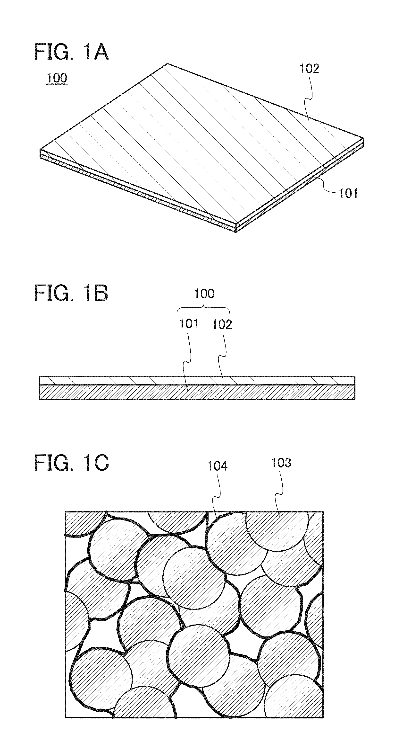
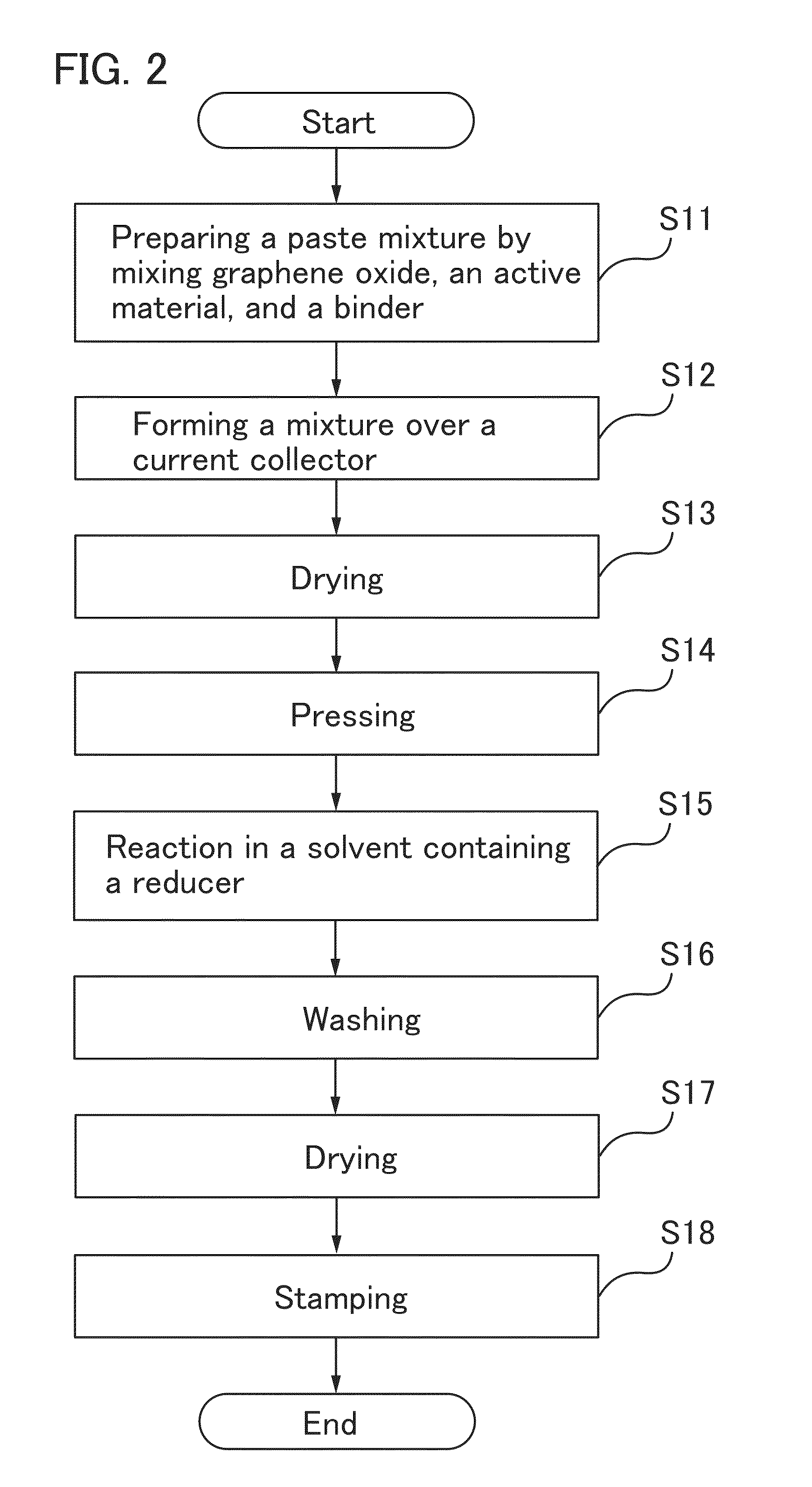
[0060]In this embodiment, a method for forming a storage battery electrode of one embodiment of the present invention will be described with reference to FIGS. 1A to 1C and FIG. 2.
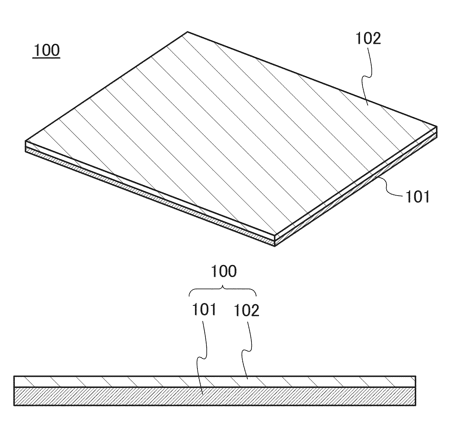
[0061]FIG. 1A is a perspective view of a storage battery electrode 100, and FIG. 1B is a longitudinal sectional view of the storage battery electrode 100. Although the storage battery electrode 100 in the shape of a rectangular sheet is illustrated in FIG. 1A, the shape of the storage battery electrode 100 is not limited thereto and may be any appropriate shape. An active material layer 102 is formed over only one surface of a current collector 101 in FIGS. 1A and 1B; however, active material layers 102 may be formed so that the current collector 101 is sandwiched therebetween. The active material layer 102 does not necessarily need to be formed over the entire surface of the current collector 101 and a region that is not coated, such as a region for connection to an electrode tab, is provide...
embodiment 2
(Embodiment 2)
[0108]In this embodiment, the structure of a storage battery including a storage battery electrode formed by the formation method described in Embodiment 1 will be described with reference to FIGS. 3A and 3B, FIG. 4, and FIGS. 5A and 5B.
(Coin-type Storage Battery)
[0109]FIG. 3A is an external view of a coin-type (single-layer flat type) storage battery, and FIG. 3B is a cross-sectional view thereof.
[0110]In a coin-type storage battery 300, a positive electrode can 301 doubling as a positive electrode terminal and a negative electrode can 302 doubling as a negative electrode terminal are insulated from each other and sealed by a gasket 303 made of polypropylene or the like. A positive electrode 304 includes a positive electrode current collector 305 and a positive electrode active material layer 306 provided in contact with the positive electrode current collector 305. A negative electrode 307 includes a negative electrode current collector 308 and a negative electrode a...
embodiment 3
(Embodiment 3)
[0129]A storage battery including the storage battery electrode of one embodiment of the present invention can be used for power supplies of a variety of electrical devices driven by power.
[0130]Specific examples of electrical devices each utilizing a storage battery including the storage battery electrode of one embodiment of the present invention are as follows: display devices of televisions, monitors, and the like, lighting devices, desktop personal computers and laptop personal computers, word processors, image reproduction devices which reproduce still images and moving images stored in recording media such as digital versatile discs (DVDs), portable CD players, portable radios, tape recorders, headphone stereos, stereos, table clocks, wall clocks, cordless phone handsets, transceivers, portable wireless devices, mobile phones, car phones, portable game machines, calculators, portable information terminals, electronic notebooks, e-book readers, electronic transla...
PUM
| Property | Measurement | Unit |
|---|---|---|
| temperature | aaaaa | aaaaa |
| interlayer distance | aaaaa | aaaaa |
| interlayer distance | aaaaa | aaaaa |
Abstract
Description
Claims
Application Information
 - R&D
- Intellectual Property
- Life Sciences
- Materials
- Tech Scout
- Unparalleled Data Quality
- Higher Quality Content
- 60% Fewer Hallucinations
Browse by: Latest US Patents, China's latest patents, Technical Efficacy Thesaurus, Application Domain, Technology Topic, Popular Technical Reports.
© 2025 PatSnap. All rights reserved.Legal|Privacy policy|Modern Slavery Act Transparency Statement|Sitemap|About US| Contact US: help@patsnap.com


