Electrical control system

a technology of electrical control system and control system, which is applied in the direction of motor/generator/converter stopper, dynamo-electric converter control, instruments, etc., can solve the problems of increasing motor speed, increasing electrical inefficiency of stator, and adding stress in the rotor, so as to reduce the switching of pulse width and increase the efficiency of the motor. , the effect of smoothing the alternating current waveform

Active Publication Date: 2016-01-05
BARBER-NICHOLS LLC
View PDF8 Cites 13 Cited by
  • Summary
  • Abstract
  • Description
  • Claims
  • Application Information

AI Technical Summary

Benefits of technology

[0022]Broadly, the present invention is an electrical control system that includes a direct current to direct current converter and / or regulator circuit that receives a direct current supply system power input, wherein the regulator outputs a controlled voltage direct current inverter circuit power feed. Further included in the electrical control system is an inverter circuit assembly that is in electrical communication with the regulator and receives the controlled voltage direct current inverter power feed, wherein the inverter outputs an alternating current motor power feed. Also included in the electrical control system is a permanent magnet brushless direct current motor that is in electrical communication with the inverter and receives the alternating current motor power feed, wherein the motor outputs a shaft rotational speed and a back electromotive force. In addition, for the electrical control system a means is provided for regulating the controlled voltage direct current inverter circuit power feed based upon criteria utilizing the motor shaft rotational speed and the back electromotive force to substantially make the controlled voltage proportional to the back electromotive force to reduce a pulse width modulation switching frequency to further smooth the alternating current waveform to increase motor efficiency.
[0023]Also as an alternative to the back electromotive force, an embedded auxiliary stator wire loop that generates a signal that is processed can be utilized for determining motor rotor speed and rotor position relative to the motor stator windings much as the back electromotive force does. Further a voltage look-up table can optionally be used to increase the accuracy of determining the motor rotor speed and rotor position relative to the motor stator windings for the regulator to use.

Problems solved by technology

However, increasing motor speed creates a number of design issues to overcome that primarily occur in two areas, being the motor itself and electrical control of the motor.
For the motor itself, the design issues would include structural integrity of the motor rotor to withstand high rotational speeds, motor rotor shaft bearings again to withstand high rotational speeds, clearances as between static and dynamic parts, and temperature rise considerations due to friction and electrical inefficiencies which become predominate at higher power densities, as smaller motor size equates to lower surface areas and lower volumes to absorb and shed heat buildup.
A conventional lower rotational speed motor rotor construction (typically termed squirrel cage induction), utilizes a complex multi piece built-up rotor with iron plates and copper wire windings-being limited to a maximum rotational speed of about twenty thousand revolutions per minute (20,000 rpm) due to rotational centrifugal stress and excessive heat buildup in the iron and copper due to electrical inefficiency.
Although the permanent magnet reduces the previously mentioned electrical inefficiency of the squirrel cage induction rotor, the addition of the structural reinforcement that is positioned between the high speed motor rotor and stator increases electrical inefficiency as the structural reinforcement acts as an electrical and physical barrier between the rotor permanent magnet and the rotating electromagnetic field of the stator.
The Hall effect sensor works well, however, having drawbacks of size and structure needed to accommodate the sensor in proximity to the motor rotor plus the need for an asymmetrical discontinuity in the rotor to give the sensor a “read” section for rotor speed and position.
The requirements of the sensor and asymmetrical discontinuity are generally not desirable in the high speed motor for several reasons; the sensor structure consumes physical space which on a proportional scale is problematic in a smaller high speed motor, plus in addition, the asymmetrical discontinuity in the rotor also consumes physical space and further interferes with achieving optimal rotor balance and causes added stress in the rotor, wherein desirable design in a high speed motor would dictate minimal physical structure space consumed and minimal rotor size that is completely symmetric in design.
One sensorless high speed motor solution is to use motor back electromotive force (EMF) as a way to determine motor rotor speed and rotor position while the motor is operational—i.e. the rotor is rotating, however, having the problems that no back EMF is generated when the motor rotor is stopped, which can lead to rotor position error at motor startup, which could cause reverse rotor rotation.
In contrast to this requirement, several loss mechanisms with the controller and motor are tied to the frequency content of the current waveforms, with losses tending to rise with increasing frequency or increased motor rotational speed.
This results in a trade-off between high losses and usable motor speed.
The problem with this is that it results in high switching losses and limits upon the motor rotational speed achievable.
This of course brings in a complication as this metal “can” or could be termed a structural reinforcement sleeve needs to have fairly high strength in a tensile manner and also have high electrical resistivity to minimize eddy current losses during BLDC motor operation.
The sine wave controller with prior art sine wave filters is typically large, expensive, and inefficient with a limited optimum speed range.
Utilizing simple block commutation as previously described with a high-speed metal structural sleeve banded motor rotor results in current waveforms and subsequent motor air gap flux profiles that cause excessive rotor heating and thus motor inefficiency.
The difficulty with maintaining this condition is that the required voltage changes with every change to the desired speed of the motor output shaft and further with a shaft load at that speed, thus being a very dynamic condition.
In addition, this operating mode will dramatically limit the available power at a low motor shaft output speed due to the linear relationship between speed and output voltage.

Method used


Image

  • Electrical control system
  • Electrical control system
  • Electrical control system

Examples


embodiment 52

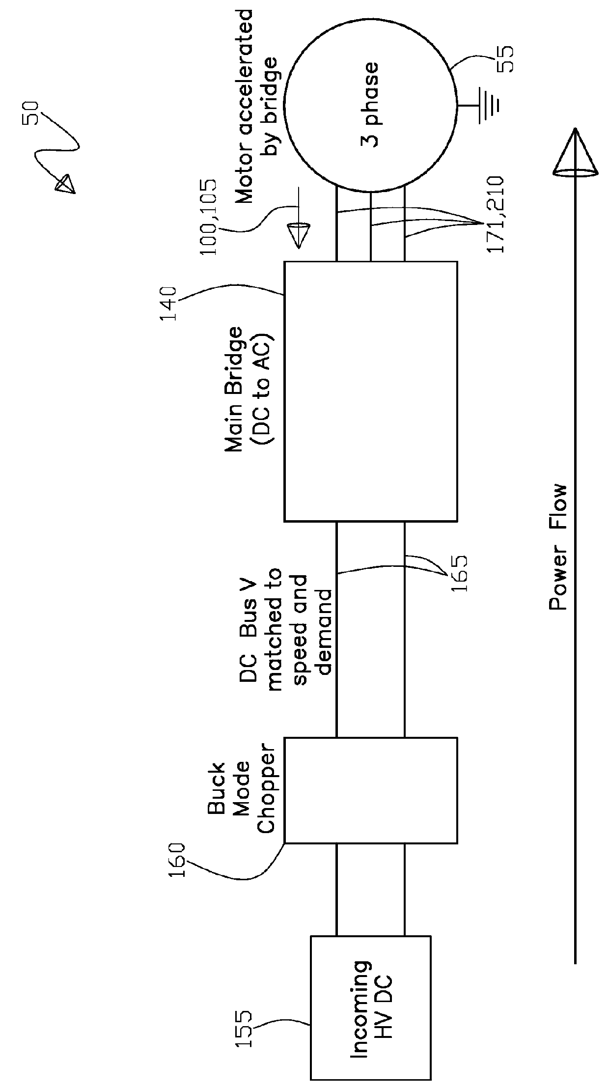
[0120]Further, FIG. 15 shows a schematic block diagram of the second alternative embodiment 52 for the present invention electrical control system that includes a higher voltage direct current supply system power input 155. Continuing, FIG. 15 shows a direct current to direct current converter regulator circuit 160, a controlled voltage direct current inverter circuit power feed 165, the inverter circuit assembly 140, a lower pulse width modulation smoothed three phase alternating current 171, for a smoothed lower harmonic wave form 210 (not shown), and the high speed permanent magnet motor 55 with a signal 101 generated from the auxiliary stator wire loop 106 (not shown) disposed within the stator wire windings 126 (not shown).

embodiment 53

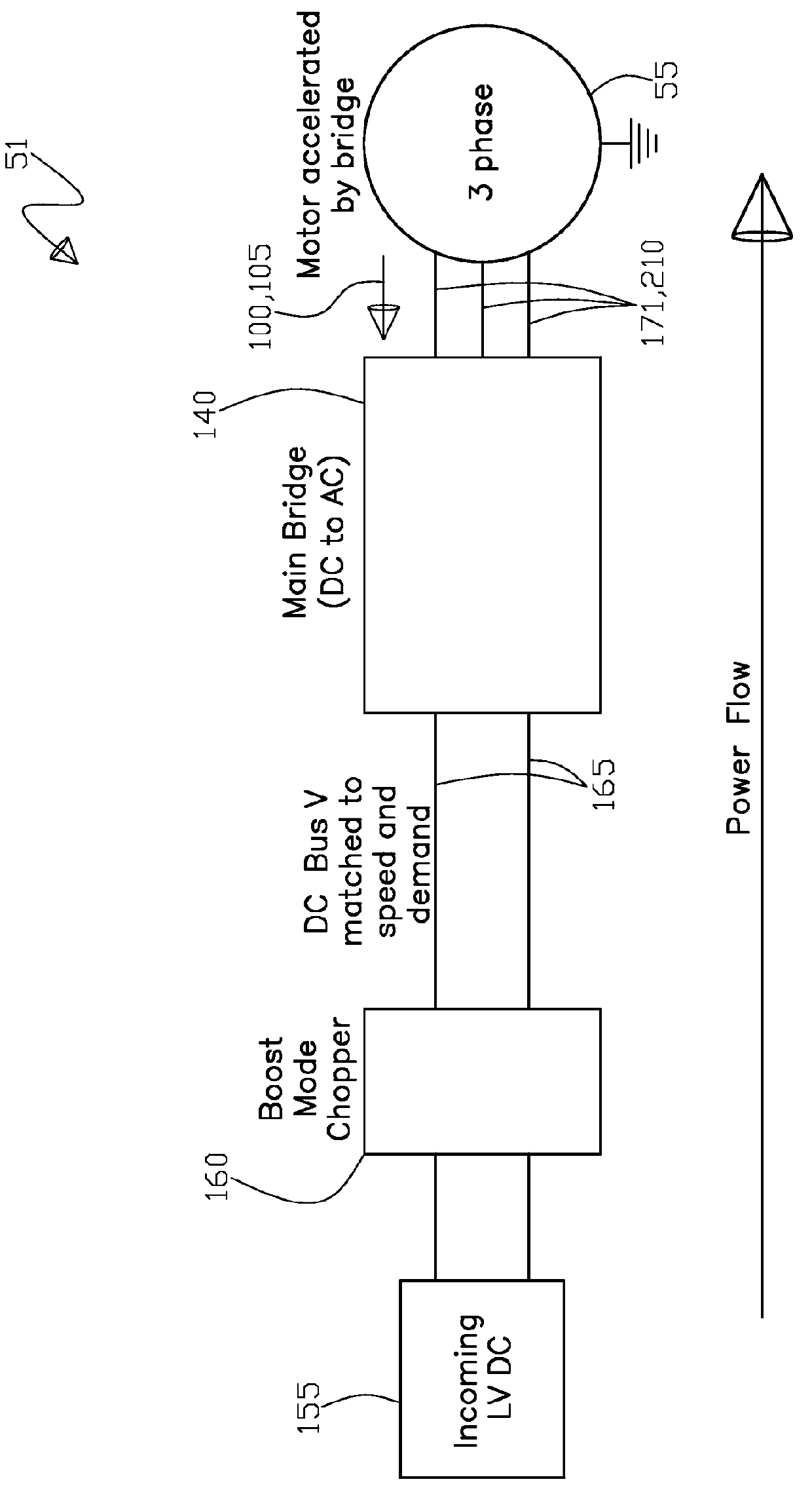
[0121]Next, FIG. 16 shows a schematic block diagram of a third alternative embodiment 53 of the present invention electrical control system that includes a lower voltage direct current supply system power input 155. Also, FIG. 16 shows a direct current to direct current converter regulator circuit 160, a controlled voltage direct current inverter circuit power feed 165, the inverter circuit assembly 140, a lower pulse width modulation smoothed three phase alternating current 171 for a smoothed lower harmonic wave form 210 (not shown), and the high speed permanent magnet motor 55 with a signal 101 generated from the auxiliary stator wire loop 106 (not shown) disposed within the stator wire windings 126 (not shown).

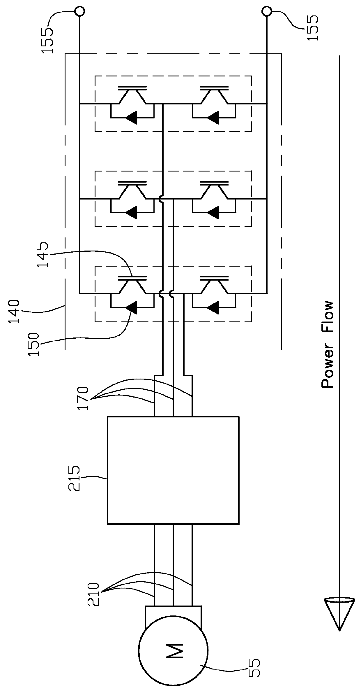
[0122]Continuing, FIG. 17 shows an expanded schematic view of FIG. 15, of the second alternative embodiment 52 for the present invention electrical control system that includes a higher voltage direct current supply system power input 155. Further, FIG. 17 shows a direct cu...


PUM


Abstract

An electrical control system having a direct current to direct current regulator receiving a direct current supply input, wherein the regulator outputs a controlled voltage direct current inverter power feed. Included is an inverter in electrical communication with the regulator and receives the controlled voltage direct current inverter power feed, the inverter outputs an alternating current motor power feed to a permanent magnet brushless direct current motor that outputs a shaft rotational speed and a back electromotive force. Also, a control is provided for regulating the controlled voltage direct current inverter power feed based upon criteria utilizing the back electromotive force or an auxiliary motor stator wire loop signal in conjunction with an optional voltage look-up table to substantially make the controlled voltage result in a reduction of a pulse width modulation switching frequency to further smooth and reduce harmonic of the alternating current waveform to increase motor efficiency.

Description

RELATED PATENT APPLICATION[0001]This application claims the benefit of U.S. provisional patent application Ser. No. 61 / 647,230 filed on May 15, 2012 by Robert Lyle Fuller of Conifer, Colo., U.S. and David J. Wehrlen of Evergreen, Colo., US.TECHNICAL FIELD[0002]The present invention relates generally to a system for controlling electrical power. More specifically, the present invention relates to the field of matched electrical power control circuitry to an electrical power device for assisting in increasing the efficiency of the electrical power device.BACKGROUND OF INVENTION[0003]In the ever present desire to reduce the size and weight of components, especially those that are in mobile applications, such as a vehicle for instance, the reduction of component size and weight while maintaining or improving overall component functionality is highly desirable. To effectuate this component size and weight reduction while at least maintaining component functionality, the power density of ...

Claims


Application Information

Patent Timeline
Patent Type & Authority Patents(United States)
IPC IPC(8): H02P6/10B60L3/00B60L15/04B60L15/08B60L15/20H02P6/08H02M1/12H02M3/158H02M1/00
CPCH02P6/10B60L3/0061B60L15/04B60L15/08B60L15/20B60L2210/14B60L2210/40B60L2220/14B60L2220/16B60L2240/421B60L2240/423B60L2240/425B60L2240/427B60L2240/429B60L2240/527B60L2240/529H02M1/12H02M3/158H02M2001/007H02M2001/0048H02P6/085Y02B70/1491H02M1/0048H02M1/007Y02T10/64Y02T10/72Y02T90/16Y02B70/10
Inventor FULLER, ROBERT LYLEWEHRLEN, DAVID J.
Owner BARBER-NICHOLS LLC
Why Eureka
Try Eureka