Solid oxide fuel cell device

a fuel cell and solid oxide technology, applied in the direction of fuel cells, fuel cell details, electric generators, etc., can solve the problems of remarkable deterioration of power generation efficiency, leakage of fuel gas and oxidant gas, cracks to occur and develop in the ag, etc., to achieve high power generation efficiency and output, and prevent the effect of degradation

Active Publication Date: 2016-02-02
MORIMURA SOFC TECH CO LTD
View PDF11 Cites 1 Cited by
  • Summary
  • Abstract
  • Description
  • Claims
  • Application Information

AI Technical Summary

Benefits of technology

[0024]According to the present invention, the dense body is at least partially formed over at least either the fuel gas side of the Ag seal portion or the oxidant gas side of the Ag seal portion for separating the fuel gas and the oxidant gas. This can effectively prevent degradation of Ag such pores or cracks in the Ag seal portion, and resulting contact between the fuel gas and the oxidant gas leading to production of water. Thus, even when the Ag material is used as a gas seal structure for separating the fuel gas and the oxidant gas, the degradation can be prevented. As a result, leaks and contact of the fuel gas and the oxidant gas as well as the porosity with expansion of the Ag seal portion can be prevented to maintain high power generation efficiency and output of the SOFC.

Problems solved by technology

However, for example, as shown in Non Patent Literature 1, pores will be generated wholly inside the Ag due to water (water vapor) which is generated by the reaction of hydrogen and oxygen that are diffused in the Ag, when the Ag, which is contacted by both reducing atmosphere and oxidizing atmosphere, is heated to about 500° C. The pores, which are mainly formed along a grain boundary, will cause cracks to occur and develop in the Ag due to contact between the pores and portions where water (water vapor) occurs.
Thus, the Ag degrades over time while the Ag expands (in other words “the porosity with Ag expansion”), leading to leaks of fuel gas and oxidant gas.
The two gases, which are mixed and reacted to produce water, are consumed ineffectually, resulting in remarkable deterioration of power generation efficiency.

Method used


Image

  • Solid oxide fuel cell device
  • Solid oxide fuel cell device
  • Solid oxide fuel cell device

Examples


Embodiment Construction

[0045]Now, embodiments of the present invention will be described with reference to the drawings. For easy understanding of the description, the same components are denoted by the same reference numerals as much as possible in the drawings, and overlapping descriptions will be omitted. Proportions are not limited to those in the drawings. Further, the embodiments described below are exemplary for describing the present invention, and are not intended to limit the present invention to the embodiments only. Further, many variations may be made to the present invention without departing from the gist of the present invention.

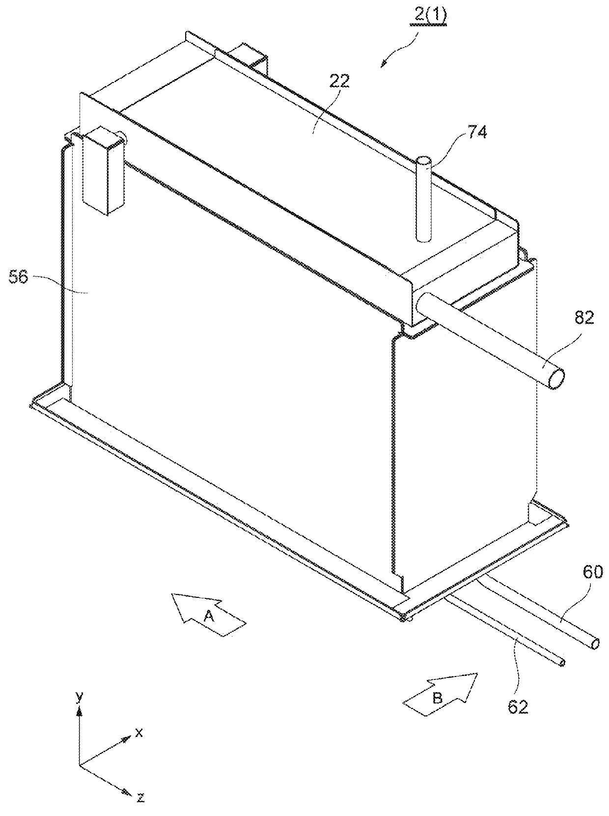
[0046]FIG. 1 is a perspective view schematically showing an appearance of an SOFC device according to a preferable embodiment of the present invention. A fuel cell module 2 constitutes a part of the SOFC device 1 according to the present invention. The SOFC device 1 includes the fuel cell module 2, and an accessory unit (not shown).

[0047]In FIG. 1, an x-axis, a y-a...


PUM

PropertyMeasurementUnit
temperatureaaaaaaaaaa
poweraaaaaaaaaa

Abstract

In a fuel cell unit 16 that constitutes a fuel cell module 2 of an SOFC device 1, a collector cap 86a is connected to an inner electrode layer 90 via a seal material 96 as an Ag seal portion. A glass coating 30 (dense body) is filled up between the inner electrode layer 90 and an electrolyte layer 94 and the collector cap 86a to cover an upper end surface 96a of the seal material 96. As such, the fuel cell unit 16 includes the seal material 96 constituting as an Ag seal portion that separates a fuel gas from an oxidant gas, and a glass coating 30 at least partially formed to over at least either the fuel gas side surface of the seal material 96 or an the oxidant gas side surface of the seal material 96.

Description

TECHNICAL FIELD[0001]The present invention relates to a solid oxide fuel cell device that generates power by using fuel gas and oxidant gas.BACKGROUND ART[0002]A solid oxide fuel cell (hereinafter also referred to as “SOFC”) is a fuel cell device including an oxygen ion conductive solid electrolyte as an electrolyte, and two electrodes that are mounted to opposite sides of the electrolyte. Fuel gas is supplied to one electrode, and oxidant gas (air, oxygen, or the like) is supplied to the other electrode, and a power generation reaction is caused at a relatively high temperature to thereby generate power.[0003]Specifically, the SOFC generally includes a fuel cell assembly (fuel cell stack) having a plurality of tubular fuel cells each including a fuel electrode (anode) layer, an air electrode (cathode) layer, and a solid electrolyte layer held therebetween. The SOFC is actuated by fuel gas and oxidant gas (air, oxygen, or the like) flowing from one side to the other side of the fuel...

Claims


Application Information

Patent Timeline
Patent Type & Authority Patents(United States)
IPC IPC(8): H01M8/02H01M8/12H01M8/24H01M8/00
CPCH01M8/0282H01M8/004H01M8/0252H01M8/1213H01M8/243Y02E60/521Y02E60/525Y02E60/50H01M8/0271
Inventor KAKINUMA, YASUOKAWAKAMI, AKIRASAIGAN, SHUICHIROANDO, SHIGERUKOBAYASHI, CHIHIROOTA, MASATOWATANABE, NAOKIISAKA, NOBUOTAKAHASHI, YUYASHIMAZU, MEGUMI
Owner MORIMURA SOFC TECH CO LTD
Why Eureka
Try Eureka