Non-contact magnetic drive assembly with mechanical stop elements

a technology of mechanical stop elements and magnetic drive assemblies, which is applied in the direction of gearing details, manufacturing tools, and evaporation chambers, can solve the problems of the integrated circuit resulting, affecting the quality of the deposited metallic layer, and limited torque available to drive the system, so as to reduce the amount of particulate contamination and increase the throughput

Active Publication Date: 2016-03-08
FERROTEC (USA) CORP
View PDF8 Cites 1 Cited by
  • Summary
  • Abstract
  • Description
  • Claims
  • Application Information

AI Technical Summary

Benefits of technology

[0012]Therefore, what is needed is a drive system that combines the advantages of both a non-contact magnetic drive system and a positive / mechanical drive system while minimizing the disadvantages of each system, i.e. a positive / mechanical drive system and a non-contact, magnetic drive system. The present invention provides improvements to the drive assemblies of deposition systems by combining the non-contact benefits of a magnetic drive system with the higher torque and positive drive capability of a mechanical drive system while preventing decoupling of the magnets in the non-contact magnetic drive system.
[0031]In still another embodiment of the present invention, a method of increasing throughput in a lift-off process vacuum deposition system while minimizing particulate contamination and incomplete batching of silicon wafers is disclosed. The method includes obtaining a non-contact, magnetic drive HULA assembly with mechanical stop elements and installing the HULA assembly in a vacuum chamber of a lift-off process vacuum deposition system. The obtaining step includes selecting a non-contact, magnetic drive HULA assembly with mechanical stop elements where a plurality of magnets are coupled in an annular orientation to each of a central ring and an orbital ring that provides for each of the plurality of orbital ring magnets in turn becoming superposed with a corresponding magnet of the plurality of central ring magnets as the orbital ring rotates about an orbital ring central axis. It further includes selecting an assembly that includes a central drive component that is adapted to drive one of the central ring, the orbital ring around the central ring or both simultaneously. The selecting step also includes selecting a central drive component that provides a rotational speed allowing non-contact, magnetic drive rotation of the orbital ring around the central ring until a difference between a magnetic drive torque provided by the superposed magnets of the central ring and the orbital ring and the rotational speed of the central drive component causes the superposed magnets to decouple. Upon decoupling of the superposed magnets, the assembly then enables mechanical drive rotation by interactive contact between a plurality of central ring teeth and a plurality of orbital ring teeth.

Problems solved by technology

Although prior art electron beam deposition systems have seen various improvements in product output, one drawback of a positive drive system in HULA systems is that physical contact between the teeth results in wear and introduces fine particles into the evaporation chamber.
If and when released, these fine metal particles contaminate or otherwise interfere with the quality of the deposited metallic layer and resulting integrated circuits.
A disadvantage of non-contact, magnetic drive systems is the limited amount of torque available to drive the system.
This limited available torque requires gentle and / or strictly controlled acceleration and deceleration profiles for the drive system to work properly.
Unfortunately, there are situations where high-torque conditions exist.

Method used


Image

  • Non-contact magnetic drive assembly with mechanical stop elements
  • Non-contact magnetic drive assembly with mechanical stop elements
  • Non-contact magnetic drive assembly with mechanical stop elements

Examples


Embodiment Construction

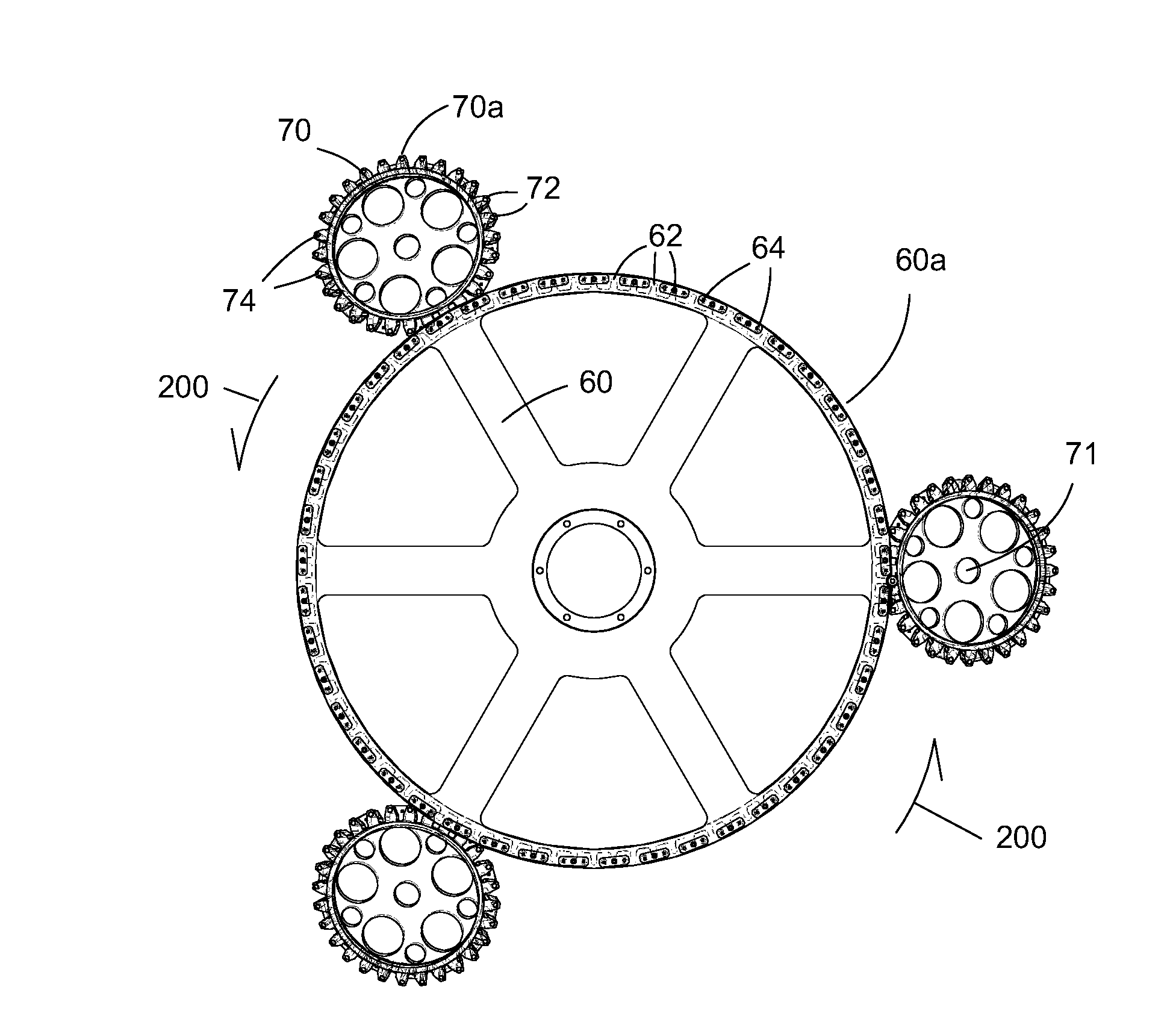
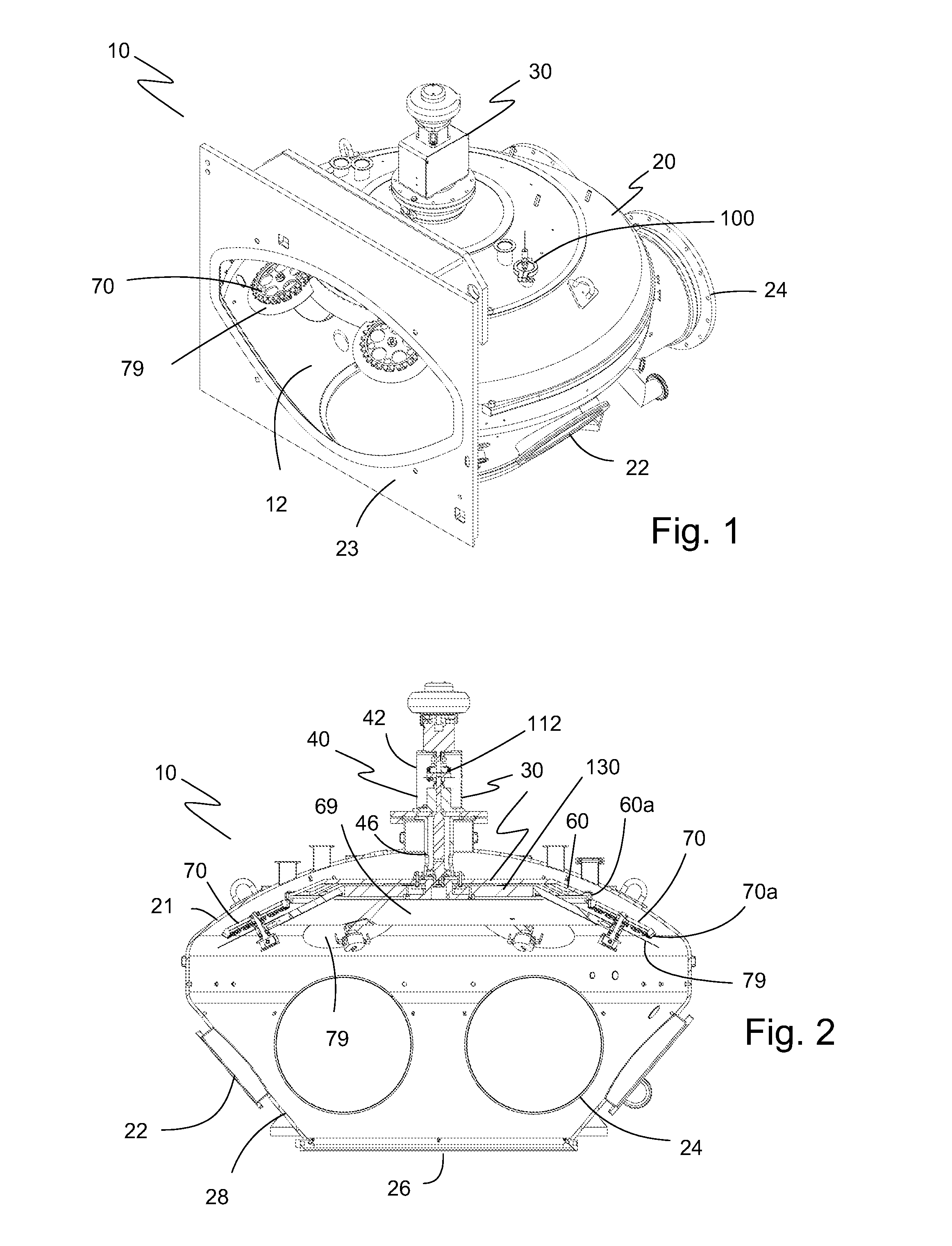
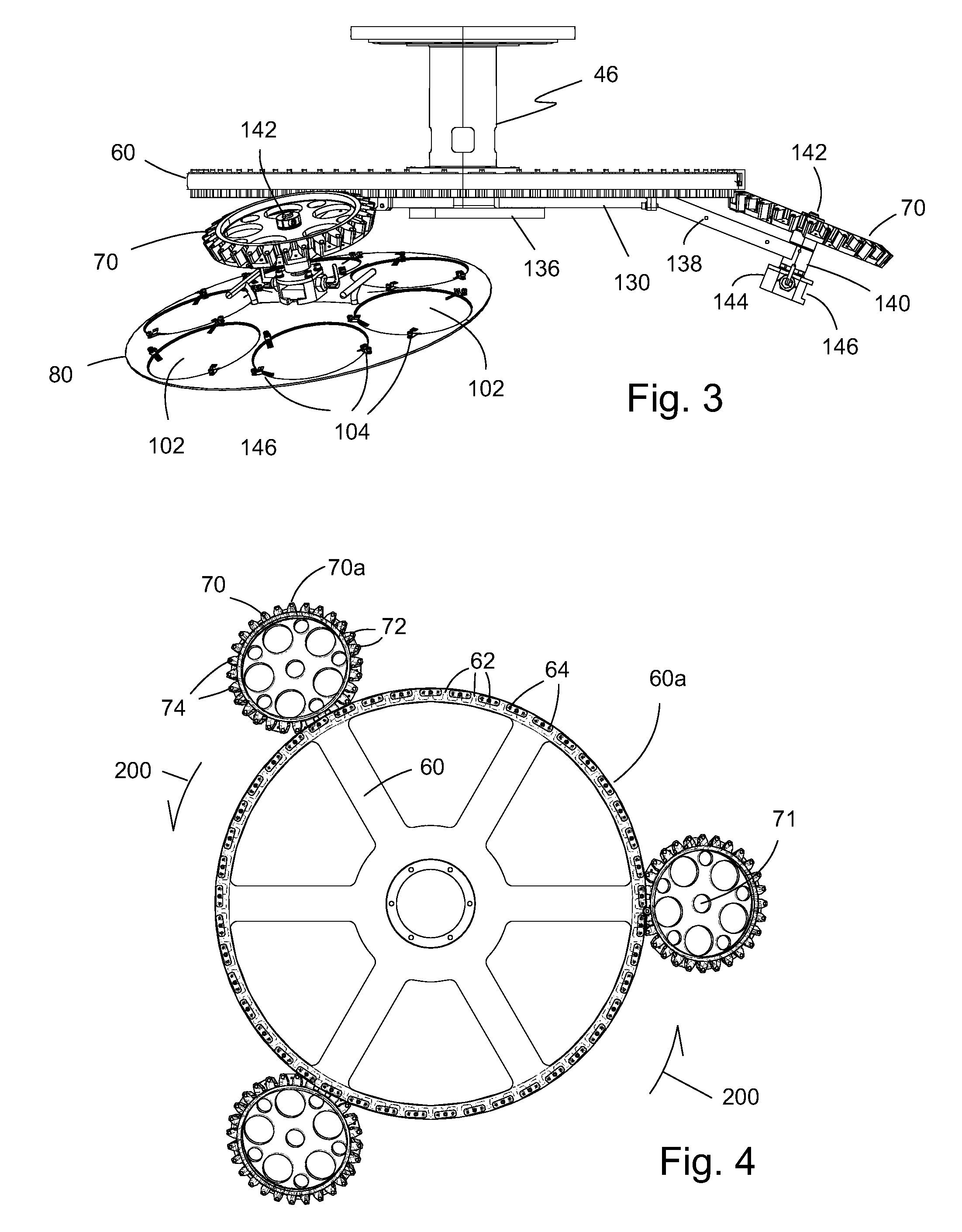
[0058]The preferred embodiments of the present invention are illustrated in FIGS. 1-14. FIG. 1 shows a perspective view of deposition chamber 10 of the present invention. Deposition chamber 10 has a chamber volume 12 defined by a chamber housing 20 where chamber housing 20 has a plurality of ports 22 and 24 for access to and / or viewing of chamber volume 12 (i.e. the inside of chamber housing 20). Chamber housing 20 has a relatively large flanged housing opening 23 compared to ports 22, 24. Connected to chamber housing 20 and rotatably disposed within chamber volume 12 is a non-contact, magnetic drive assembly 30 that employs a lift-off process using a HULA orientation. HULA means a high uniformity lift-off assembly. As part of the HULA design, one or more orbital rings 70 are disposed within chamber volume 12 where each orbital ring 70 is adapted to support / hold a substrate holder 80 (not shown). The portion of the non-contact, magnetic drive assembly 30 disposed within chamber volu...


PUM

PropertyMeasurementUnit
radial distanceaaaaaaaaaa
widthaaaaaaaaaa
rotational speedaaaaaaaaaa

Abstract

A non-contact magnetic drive assembly with mechanical stop elements for a vacuum deposition system employing a lift-off process having a HULA configuration featuring a plurality of magnets coupled in an annular orientation to a central ring and an orbital ring, each magnet of the orbital ring becomes superposed with a magnet of the central ring as the orbital ring rotates, and a central drive component driving either the central ring, the orbital ring around the central ring or both simultaneously, the central drive component provides a rotational speed allowing non-contact, magnetic drive rotation of the orbital ring around the central ring until a difference between a magnetic drive torque of the superposed magnets and the rotational speed of the central drive component causes the superposed magnets to decouple enabling mechanical drive rotation by interactive contact between a plurality of central ring teeth and a plurality of orbital ring.

Description

BACKGROUND OF THE INVENTION[0001]1. Field of the Invention[0002]The present invention relates to a vacuum treatment system for vacuum coating / deposition. Particularly, the present invention relates to a drive mechanism for a vacuum coating / deposition systems.[0003]2. Description of the Prior Art[0004]Electron beam evaporation is one method of physical vapor deposition for integrated circuit lift-off processes and optical coatings. Electron beam evaporation may be used to deposit a thin metal layer on a semiconductor wafer or other substrate. The deposited metal layer may be subsequently etched to create circuit traces of integrated circuits.[0005]Various systems have been developed using physical vapor deposition techniques. Some systems are linear systems where the target product (the substrate) is affixed to a carrier that is linearly brought into a vacuum chamber along a set of rails where the deposition apparatus, i.e. the electron gun, is located. Once the desired deposition ha...

Claims


Application Information

Patent Timeline
Patent Type & Authority Patents(United States)
IPC IPC(8): F16H1/28C23C14/50H01L21/687H01L21/67F16H57/08
CPCH01L21/68792C23C14/505H01L21/6719H01L21/68764H01L21/68771H01L21/68785F16H1/28F16H57/08Y10T29/49826
Inventor KRONEBERGER, CRISPATEL, BHARATKUMAR
Owner FERROTEC (USA) CORP
Why Eureka
Try Eureka